We remove the gearbox as described in the article - Removing and installing the gearbox gear GAZelle Next
We clean the dirt and wash the outside of the gearbox.
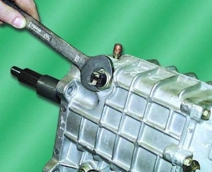
Unscrew the reverse light switch with gasket
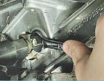
Using a 10 key, we unscrew the bolt securing the pressure sensor pressure plate
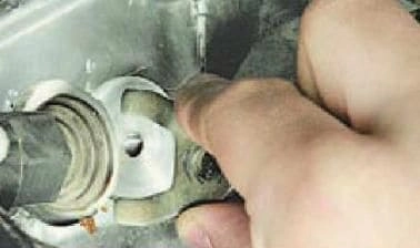
Remove the restrictive plate
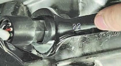
Turning left and right with the key 22 behind the sensor
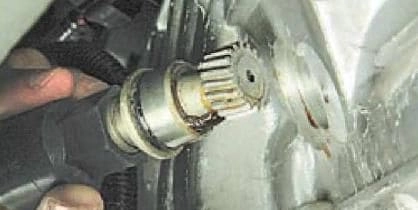
Remove the drive from the gearbox housing
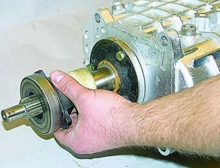
Remove the clutch with the bearing and the foam rings of the front cover
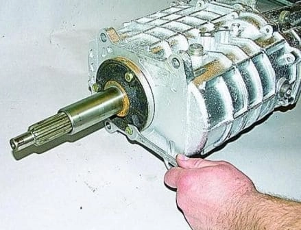
Using the “12” key, we unscrew the three bolts securing the bearing cover (the bolts are installed on the sealant).
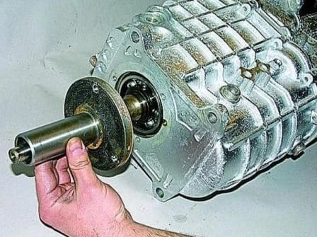
Remove the cover with the gasket.
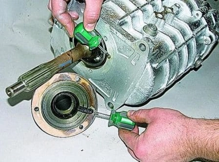
When installing it next, pay attention to the coincidence of the oil drain channel in the cover and the hole in the crankcase.
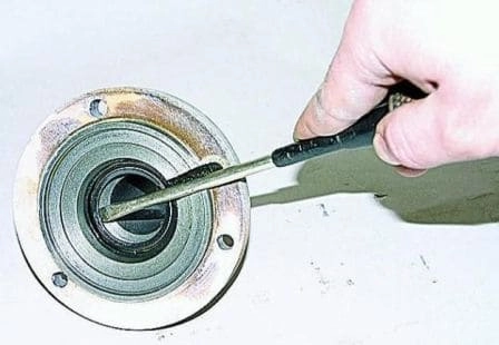
Having prying with a screwdriver, we remove the cuff of the input shaft from the cover (when disassembling the gearbox, we replace all the cuffs, regardless of their condition)
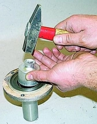
With a mandrel or a suitable diameter head, we press in a new cuff
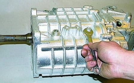
Using the “13” key, unscrew and remove the bolt securing the reverse gear axle bushing to the front crankcase
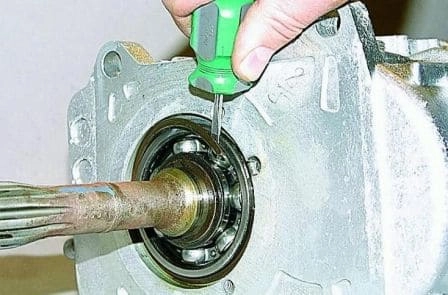
Use a thin screwdriver to pry and remove the retaining ring of the input shaft bearing
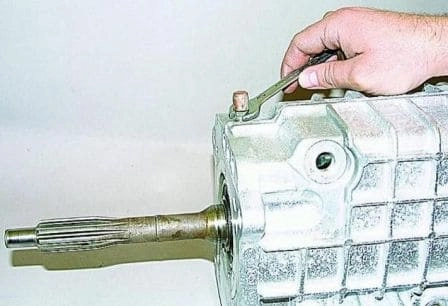
Key 12 unscrew and remove the breather
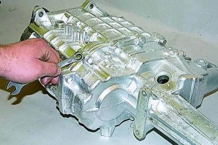
Using the “12” key, we unscrew ten bolts connecting the front and rear crankcases (two bolts passing through the mounting sleeves are longer than the others)
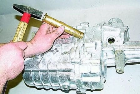
Carefully tapping with a hammer through the brass mandrel, we undock the front and rear crankcases.
In this case, it is impossible to strike the end of the input shaft, as the synchronizers will be damaged.
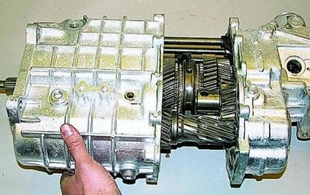
Disconnecting the gearbox housings.
Carefully, trying not to damage, remove the gasket.
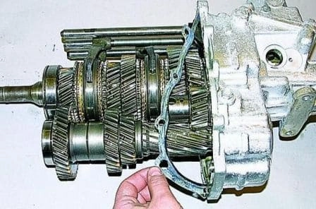
We take out the shims from the bore for the intermediate shaft bearing in the front crankcase (they may not be there).
In this case, the axial clearance in the bearings is set only by an inter-crankcase seal.
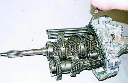
Turning the input shaft, we turn on the reverse gear (we move the rod of the V gear and reverse gear forward)
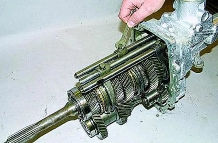
Using the “10” key, we unscrew the bolts securing the three gear shift forks
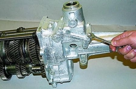
Using the “12” key, we unscrew the four bolts securing the gear lever housing
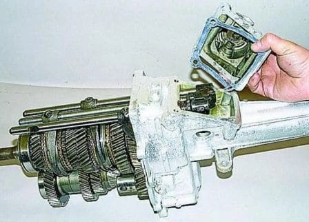
Remove the lever housing with gasket
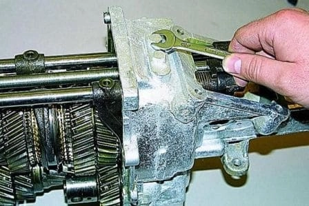
Using the “12” key, we unscrew the bolts securing the plate of the rod retainers
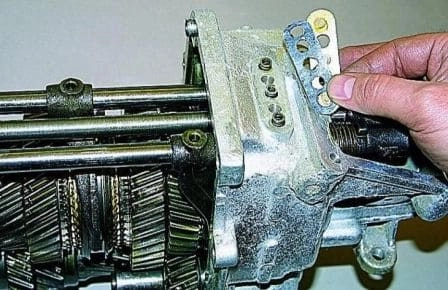
Remove the plate with the gasket
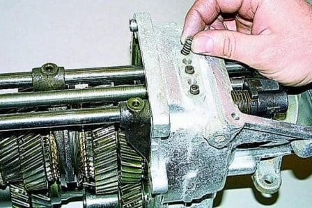
We take out three springs and three balls of gear detents (they can be removed with a magnetized screwdriver or by turning the box over)
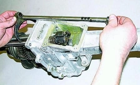
We take out the stem of the I-II gear (in order not to mix it up during assembly, we immediately put the fork on the stem and fasten it with a bolt).
We take out the rod of the V gear and the reverse gear, putting on it the corresponding fork.
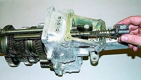
Remove the stem of III-IV gears.
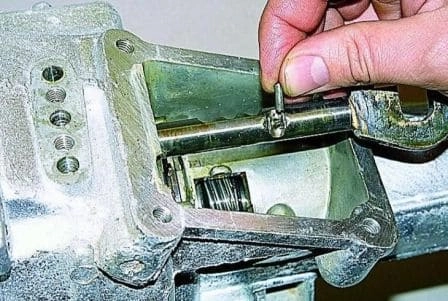
Remove the blocker pin from the stem.
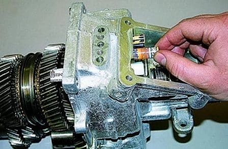
To prevent the blocker plungers from falling out, we insert tubes folded from thick paper into the holes of the rods.
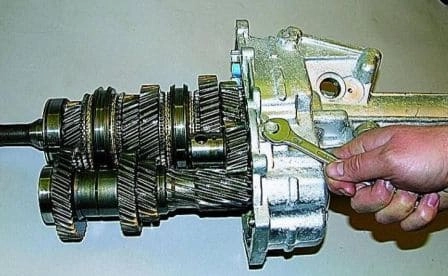
Using the “13” key, we unscrew the bolt securing the reverse gear axle to the rear crankcase.
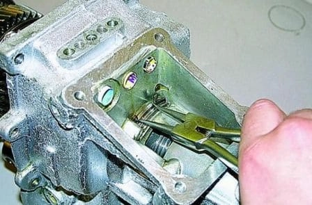
Using tongs, we spread the antennae of the retaining ring of the rear bearing of the secondary shaft and, tapping with a copper hammer on the rear end of the secondary shaft
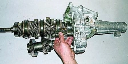
we take out the set of shafts together with the axle and the reverse gear.
Disconnect the primary and secondary shafts.
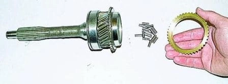
Remove the IV gear synchronizer and take out 14 rollers of the front support of the secondary shaft.
Gears, synchronizers and other parts located on the primary and secondary shafts are similar to each other, therefore, to facilitate subsequent assembly, they should be carefully laid out in the order of removal.
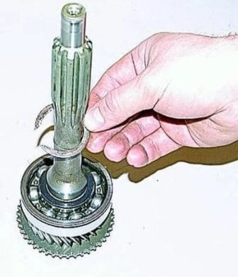
With two thin screwdrivers or special tongs, we open and remove the retaining ring from the input shaft
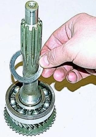
Remove the snap ring
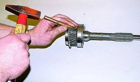
With a beard (two mounting blades or a special puller), we compress the input shaft bearing
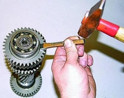
We also remove both intermediate shaft bearings
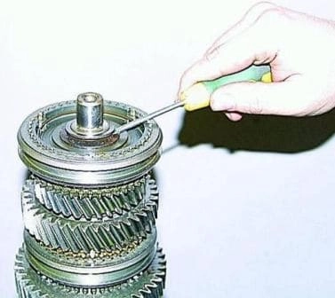
Having installed the secondary shaft vertically in a vise through soft gaskets, remove the retaining ring
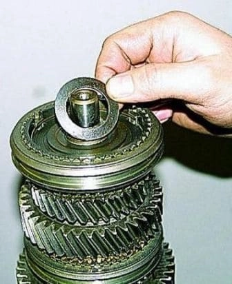
Remove the spring ring of the III–IV gear clutch hub
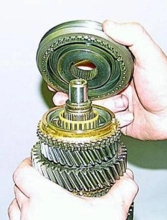
Remove the clutch assembly with crackers and synchronizer springs.
It is better not to disassemble this kit, but if such a need arises, mark the relative position of the parts.
Gear clutches are not symmetrical, so they only fit in one position.
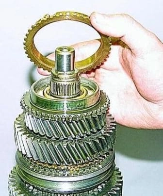
Remove the synchronizer ring
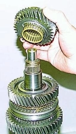
Remove the third gear along with the plastic separator and rollers
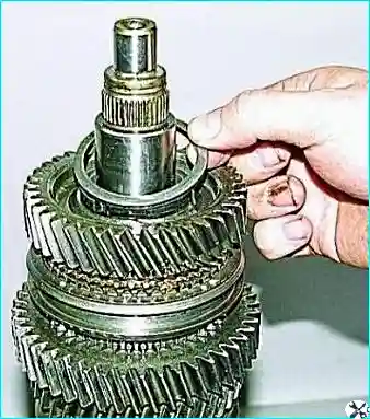
Use a screwdriver to pry off and remove the retaining ring
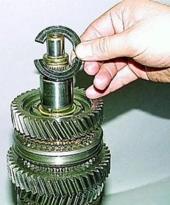
Remove two persistent half rings
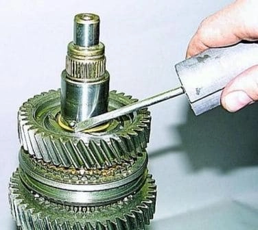
Use a magnetized screwdriver to remove the locking ball of the half rings
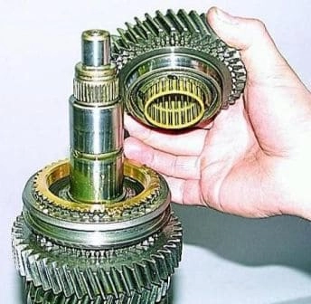
Remove the 2nd gear gear with bearing
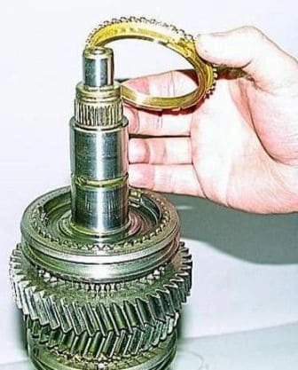
Remove the 2nd gear synchronizer ring
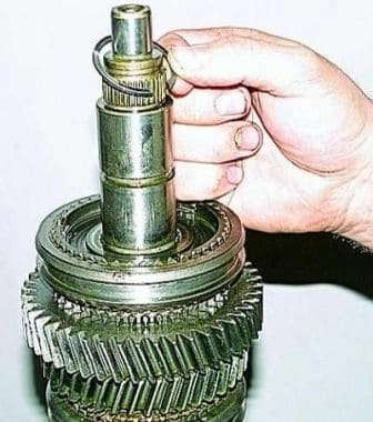
Remove the retaining ring
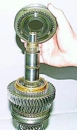
Remove the I-II gear clutch
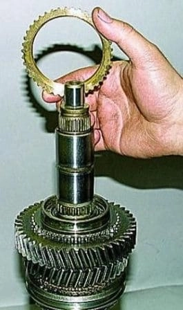
Remove the 1st gear synchronizer ring
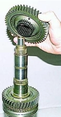
Remove the 1st gear gear with bearing.
Further disassembly of the secondary shaft is carried out from the other end
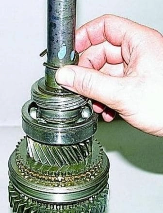
Prying off with a thin screwdriver, remove the retaining ring
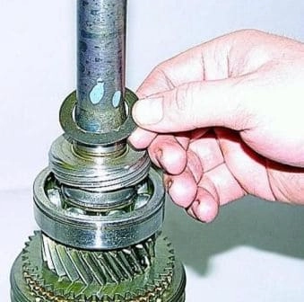
Remove the snap ring
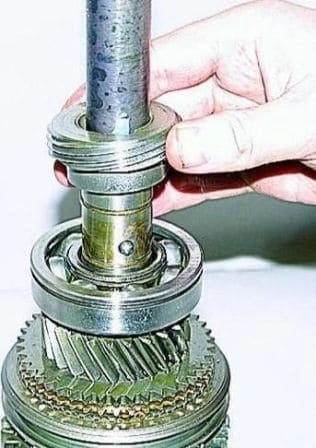
Remove the speedometer drive gear and take out its locking ball
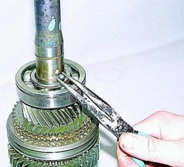
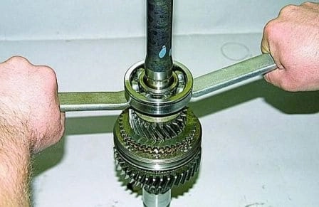
With two mounting blades or a special puller, remove the rear bearing of the secondary shaft
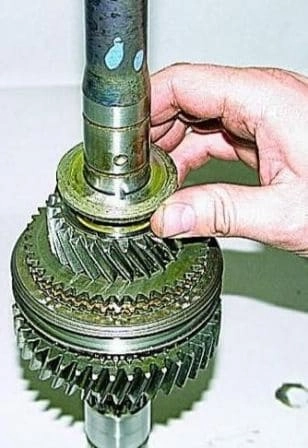
Remove the thrust washer
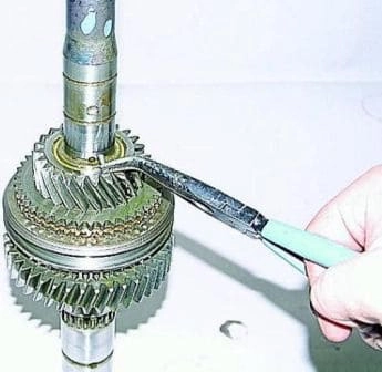
Remove the pin with pliers
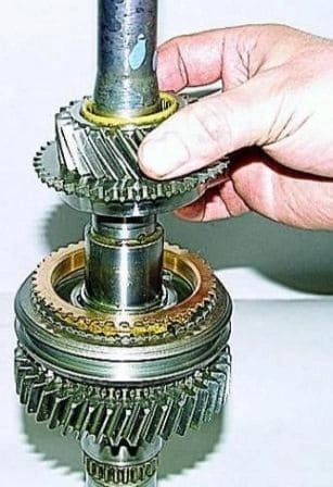
Remove the V gear with bearing and synchronizer
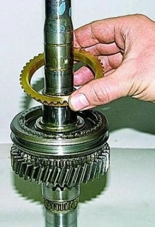
Remove the distance ring
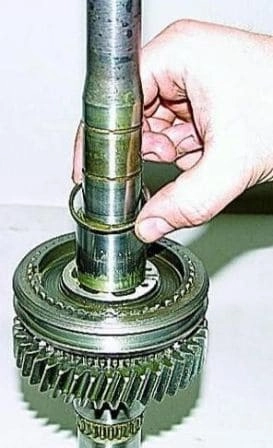
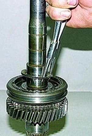
Remove the spring ring with special pliers and screwdrivers
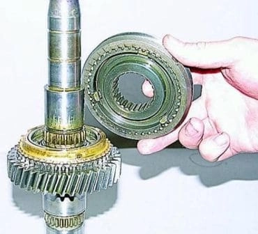
Remove the 5th gear and reverse clutch
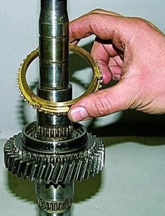
Remove the synchronizer ring
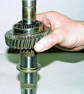
Remove the reverse gear with bearing
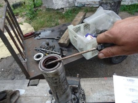
Remove two cuffs from the rear crankcase extension
We look at the gearbox assembly in the following article - Defection and assembly of the gearbox gear GAZelle Next


