Before assembly, check the condition of the gearbox parts.
Cracks of any shape and length are not allowed on crankcase parts
The bearing housings, shift rod holes, and the steel-babbit bushing of the rear crankcase extension must be smooth and free of nicks, nicks, or noticeable wear.
When assembling, we are guided by the article on disassembling the gearbox (article - Disassembling the gearbox of a car Gazelle Next), as you need to assemble the box in reverse order
The bearings should fit into the sockets tightly, by hand force or by light tapping through the spacer.
Crankcase gaskets must be intact, without breaks, delaminations and breaks.
We check the shafts, axles and rods for the absence of cracks, noticeable signs of wear, scuffing and metal enveloping.
This also applies to the splined parts of the shafts, the mating parts should move easily on the shafts, without noticeable backlash and jamming.
Remove minor traces of scuffing, as well as possible corrosion (on splines), with a velvet file, very fine sandpaper, and polish the shaft necks with thin GOI paste or diamond paste.
On the teeth of gears and synchronizer couplings, chips, signs of seizing and chipping are not allowed, on the cones of synchronizers there should also be no signs of seizing, severe wear and enveloping of bronze on steel.
Ball and roller bearings must be in perfect condition.
Their rotation should be easy, without jamming, clicking, play and vibration.
Fatigue chipping (pitting), noticeable wear and chips are not allowed on the raceways, balls and rollers (needles).
The cages of ball bearings must not touch the rings, have cracks and breaks.
In general, after a run of about 100 thousand km, it is better to replace ball bearings, regardless of their condition.
We also replace the cuffs of the sliding fork of the propeller shaft and the cuff of the input shaft, regardless of their condition.
Before assembling, we thoroughly wash all parts in kerosene or diesel fuel, degrease the crankcase threaded holes with acetone or a solvent for nitro-paints.
We cover the rubbing surfaces of the gearshift mechanism, the steel-babbit bushing, cuffs and splines of the secondary shaft with SHRUS-4 grease, the rest with gear oil.
The bearings and their seats should also be lubricated with gear oil before assembly.
Synchronizer Assembly
Lubricate the synchronizer parts with a thin layer of transmission oil.
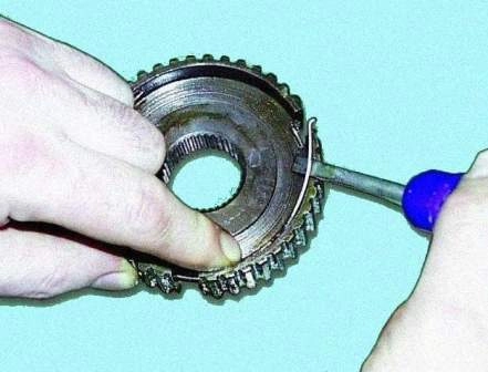
Install one spring into the synchronizer hub.
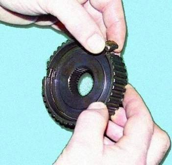
Install crackers in the synchronizer hub
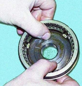
Install the sliding sleeve on the hub according to the marks
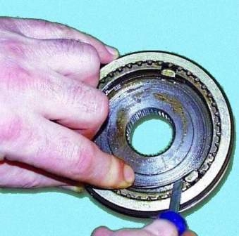
Install the second spring so that the bent ends of both springs are in the same crack, and the coils of the spring are directed in different directions
Check the ease of axial movement of the synchronizer parts.
The side clearance between the hub and the sliding sleeve should be between 0.01-0.05 mm.
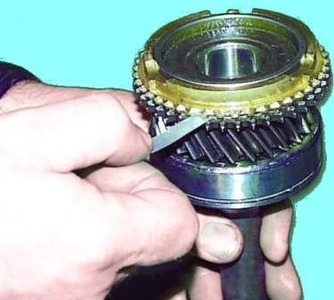
Check the gap between the gears and the corresponding locking rings, which should be between 1.1-1.5 mm.
Otherwise, the blocking ring must be replaced.
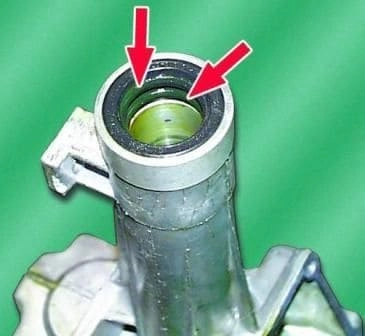
Press two oil seals into the extension of the rear crankcase flush with the end of the extension if they were filmed.
Their working edges should be directed inside the amplifier.
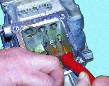
Install the mainshaft ball bearing circlip in the groove of the rear crankcase, if it was removed.
Set the 5th gear/reverse synchronizer sliding clutch on the output shaft to the reverse gear position.
Put the input shaft on the secondary shaft so that the bulk rollers do not fall out.
In this case, make sure that the protrusions of the blocking ring on the input shaft fit into the grooves of the synchronizer hub of the 3rd and 4th gears.
Connect the output shaft assembly with the input shaft in the kit, with the gear set and the axis of the reverse idle gear, engaging the corresponding gears.
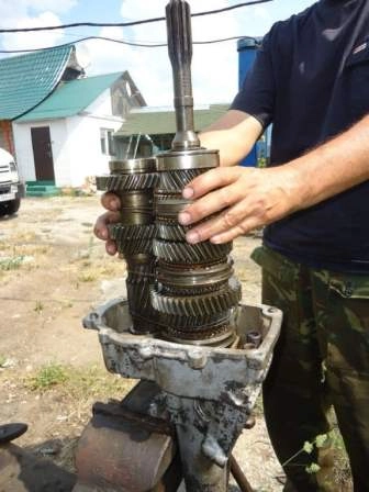
For the convenience of further installation, you can tie the resulting kit with a rope, belt or wire.
Place the back of the crankcase vertically in a vise.
Insert a set of shafts into the rear of the crankcase, open the retaining ring and press the ball bearings of the output shaft and gear assembly into the seats on the rear of the crankcase, applying force alternately to the end of the gear of the 1st gear of the output shaft and the end of the intermediate shaft until until the circlip compresses the outer ring of the ball bearing.
After that, carry out the final pressing until the retaining ring is seated simultaneously in the groove of the rear part of the crankcase and in the groove of the bearing.
Install the shaft of the reverse intermediate gear in the seat on the rear of the crankcase and tighten the mounting bolt without tightening it.
Install the rear of the gearbox housing in a horizontal position.
Insert the shift forks of the corresponding gears into the grooves of the sliding sleeves of the synchronizers.
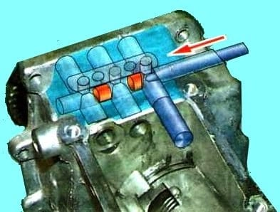
Install the locking plungers between the holes for the 3rd and 4th, 1st and 2nd and 5th gears, as well as the reverse gear.
For the installation of plungers, it is recommended to use a mandrel and a beard, but for this you will have to remove the plug and install a new one after installation.
Therefore, it is easier to try to insert plungers without a mandrel.
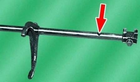
Install the locking pin in the hole of the 3rd and 4th shift rod.
Install the 3rd and 4th shift rod into the crankcase bore and the 3rd and 4th shift fork head. Fix the fork on the stem with a locking bolt.
Install the 1st and 2nd shift rod into the crankcase bore and the 1st and 2nd shift fork head. Fix the fork on the stem with a locking bolt.
Install the lock plunger all the way into the 3rd and 4th shift shaft.
Assemble the 5th gear and reverse shift rod, if it has been disassembled.
Insert the stem into the hole in the crankcase and the hole for the 5th gear and reverse shift fork.
Fix the yoke to the stem with the locking bolt.
When mounting the stem, pay attention to the correct installation of the locking sleeve spring (one end must be inserted into the hole in the wall of the rear crankcase, and the other end must be inserted into the recess of the locking sleeve so that the tab of the locking sleeve is pressed against the head of the switching rod of the 5th gear and reverse).
Set the shift rod for 5th gear and reverse to neutral.
Install the balls and springs of the detents in the appropriate holes.
Install the stem retainer plate with gasket in place and tighten the two plate fixing bolts.
If, during the repair of the gearbox, either one of the gearbox housings or the gear block (or its parts) was replaced, then it is necessary to determine the size of the thickness of the adjusting rings in order to provide the necessary axial clearance of the gear block.
After that, install a package of adjusting rings, selected according to the required thickness, into the seat of the ball bearing on the front of the crankcase.
Set the back of the crankcase with shafts in a vertical position in a vice.
Set twist a paronite gasket.
The thickness of the gasket between the gearbox housings determines the amount of axial clearance in the intermediate shaft bearings.
Therefore, we must install it, lubricating it with a thin layer of sealant for reliability.
Sealant should also be lubricated with all other cardboard gearbox gaskets.
The bolts connecting the crankcase parts should be degreased and the threads coated with sealant during assembly.
Install the front of the crankcase, aligning the appropriate holes with the locating sleeves, and press it onto the ball bearings of the input shaft and gear cluster, hitting the lugs of the front of the crankcase with a soft metal hammer.
In this case, the input shaft must be pulled up.
Tighten the ten bolts securing the front and rear crankcases evenly diagonally to a torque of 14–18 Nm (1.4–1.8 kgf m).
Note that the top two bolts are longer (M8-6gx35), the other eight bolts are M8-6gx30.
Install the circlip into the input shaft ball bearing groove.
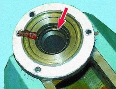
If the input shaft oil seal was replaced, then it must be pressed into the bearing cover until it stops using a mandrel.
Install the bearing cover with gasket and tighten the three fastening bolts with a torque of 14–18 Nm (1.4–1.8 kgf m).
Insert the reverse idler gear axle bolt into the front crankcase and finally tighten both axle bolts to 44–56 Nm (4.4–5.6 kgf m).
Push the breather and the reverse light switch with gasket into the front crankcase.
Install the speedometer drive with a stopper in the crankcase and tighten the stopper fastening bolt.
Insert the oil filler plug.
Install the shift lever housing with gasket and tighten the four mounting bolts to a torque of 14–18 Nm (1.4–1.8 kgf m).
Lubricate the clutch release bearing guide bush with gear oil.
Install the foam pad on the guide bushing, pre-lubricating the bushing with gear oil.
Install the release bearing with clutch on the guide sleeve.
Adjusting the axial clearance of the gear set
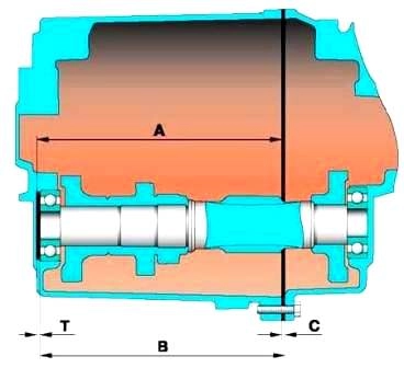
The axial clearance of the gear unit is adjusted by selecting the thickness of the adjusting rings, which provide the necessary axial clearance.
The thickness of the shim pack is determined by the formula:
T = A - 3 - B + C
where:
- - А — distance from the end of the seat for the front bearing of the gear block in the front crankcase to the rear end of the front crankcase (the mating surface with the rear crankcase), mm;
- - 3 — the required axial clearance of the gear set, equal to 0.0–0.2 mm;
- - В - distance from the front end of the rear crankcase (mating surface with the front crankcase) to the end of the outer ring of the front gear block bearing;
- - С — estimated thickness of the paronite sealing gasket between the crankcases in the compressed state, equal to 0.33 mm.
Choose a package of adjusting rings according to the calculated size T.


