
The electrical equipment of the car is made according to a single-wire circuit: the negative terminals of sources and consumers of electricity are connected to the "mass"
The function of the second wire is performed by the car body.
Electrical circuits of the engine control system are made according to the multi-wire scheme and are connected to the "ground" of the car only through the electronic control unit
Consumers are powered by a battery (when the engine is not running) and a generator (when the engine is running).
To switch the main circuits of the car, a combined ignition switch (lock) is used, consisting of a contact part and a mechanical anti-theft device with a lock.
For ease of operation and viewing, the diagrams are divided into sections of the circuit
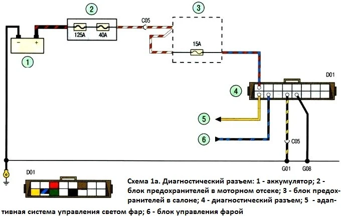 Scheme 1a
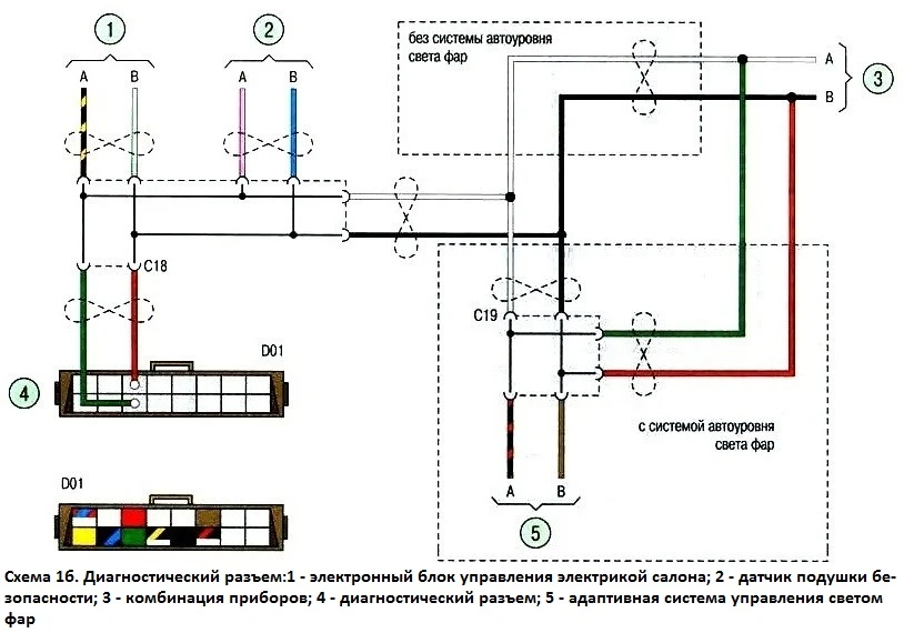 Scheme 1b
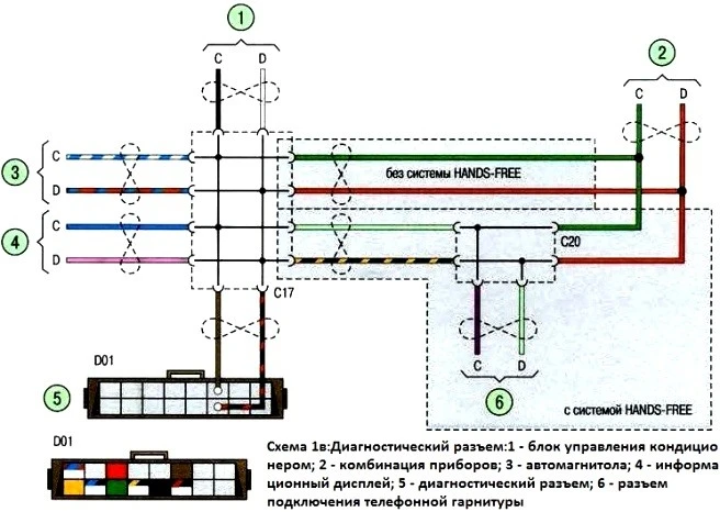 Scheme 1c
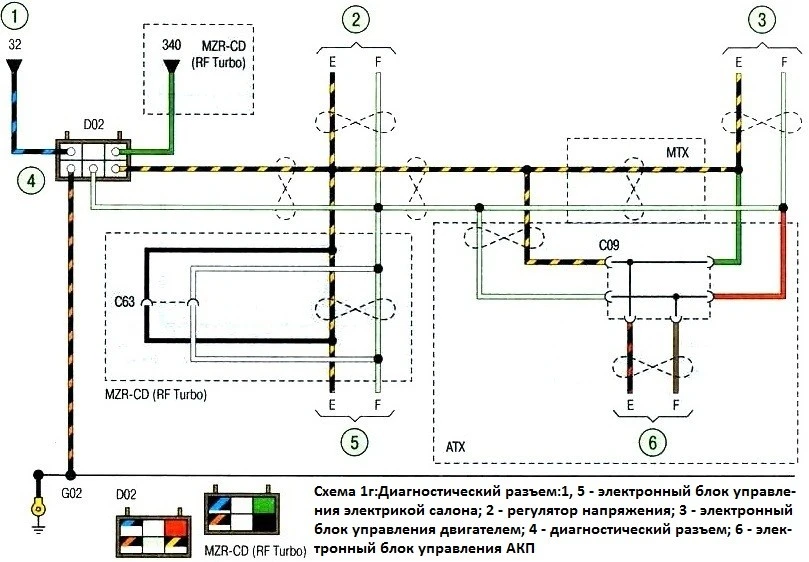 Scheme 1d
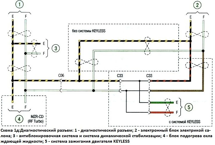 Schema 1d
Carry out any work on the electrical equipment of the car only with the battery disconnected.
Disconnect or connect the battery only when the ignition is off.
When checking the circuits of electrical equipment, it is forbidden to short the wires to ground (check the health of the circuits "for a spark"), as this can lead to failure of electrical equipment elements. It is forbidden to use fuses that are not provided for by the design of the car or designed for a higher current, and also to use wire instead of fuses.
When replacing fuses, do not use screwdrivers, as this can lead to a short circuit in electrical circuits.
It is forbidden to disconnect the battery while the engine is running in order to avoid damage to the voltage regulator and elements of the car's electronic equipment.
When carrying out electric welding on a car, it is necessary to disconnect the wires from the terminals of the battery, generator and controller.
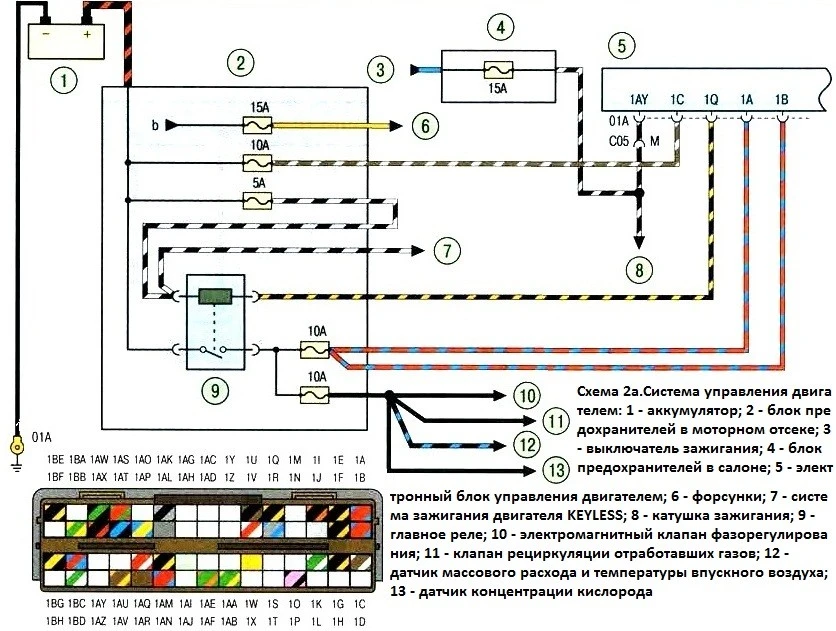 Scheme 2a
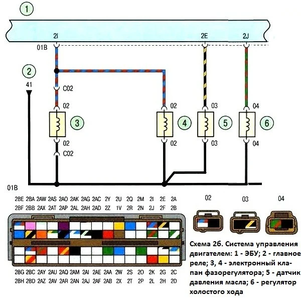 Scheme 2b
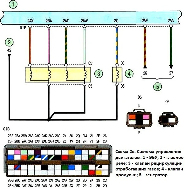 Scheme 2c
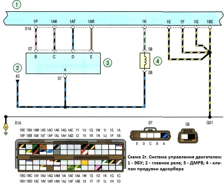 Scheme 2d
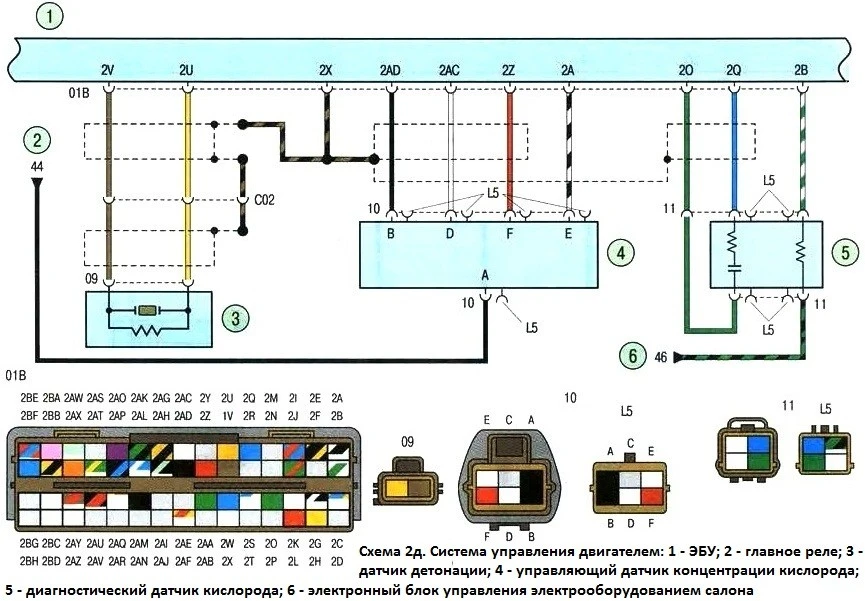 2d scheme
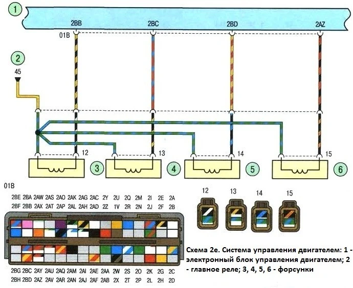 Scheme 2e
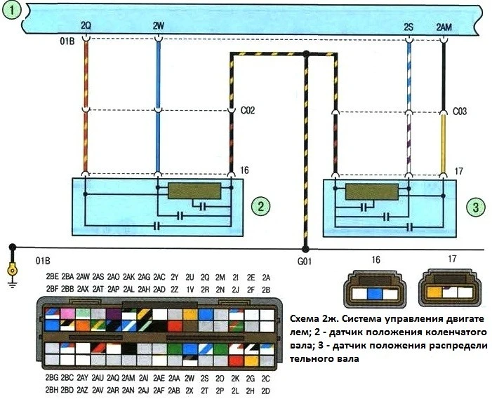 Scheme 2g
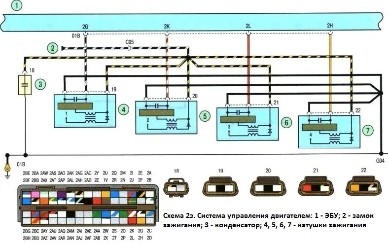 Scheme 2h
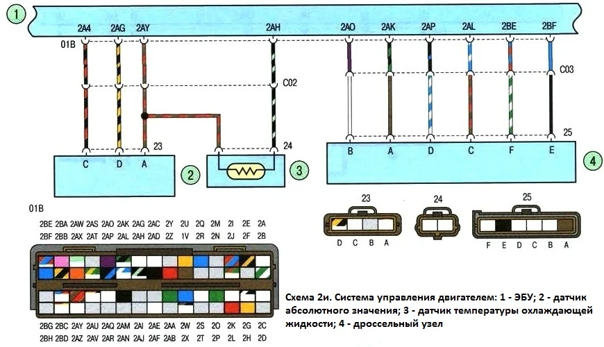 Scheme 2
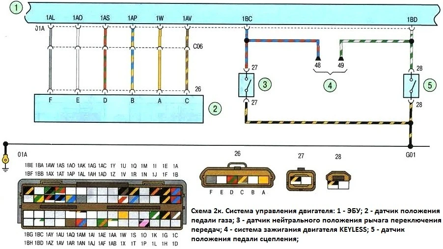 2k layout
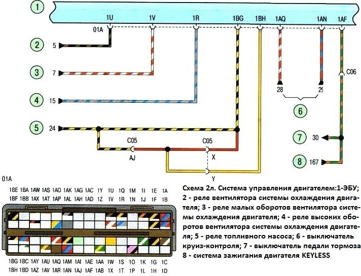 Scheme 2l
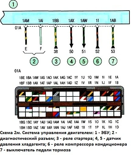 Schema 2m
A typical electrical circuit may include a main electrical element, various switches, relays, electric motors, fuses, fuses or circuit breakers related to this element, wiring and connectors used to connect the main element to the battery and ground » body.
Before you begin troubleshooting any electrical circuit, carefully study the relevant diagram to understand its function as clearly as possible
The circle of troubleshooting is usually narrowed by gradually identifying and eliminating normally functioning elements of the same circuit.
If several elements or circuits fail at the same time, the most likely cause of the failure is a blown fuse or a broken contact with the "ground" (different circuits in many cases can be closed to one fuse or ground terminal).
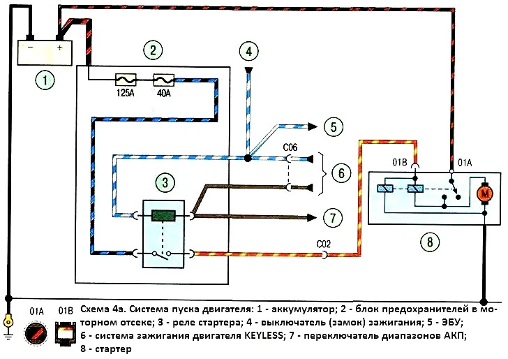
Scheme 4a. Engine start system
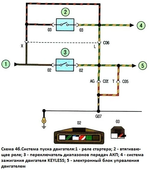
Scheme 4b. Engine start system
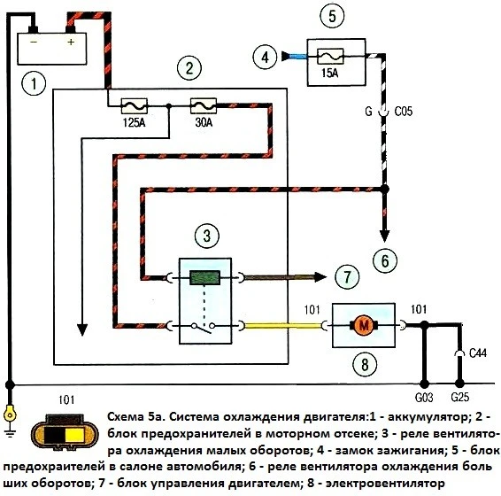
Scheme 5a. Engine cooling system
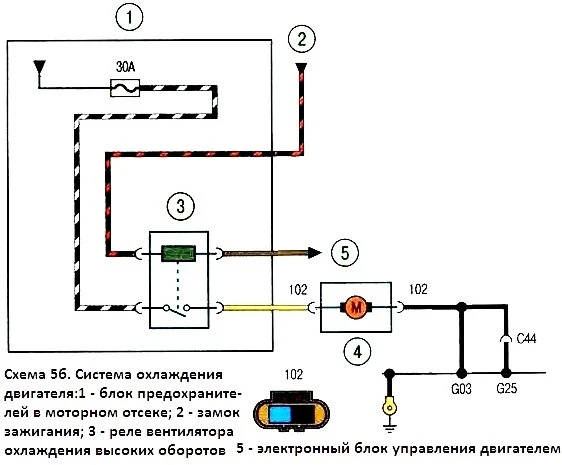
Scheme 5b. Engine cooling system
Electrical equipment failures are often due to the simplest causes, such as corrosion of connector contacts, fuse failure, fuse blown, or relay damage.
Visually check the condition of all fuses, wiring, and connectors in the circuit before proceeding to a more detailed check of the health of its components.
When using diagnostic tools for troubleshooting, carefully plan (in accordance with the attached electrical diagrams) where and in what sequence the device should be connected in the loop for the most effective troubleshooting.
The main diagnostic tools include an electrical circuit tester or voltmeter (you can also use a 12-volt test lamp with a set of connecting wires), an open circuit indicator (probe) that includes a lamp, its own power source and a set of connecting wires.
In addition, you should always have in the car a set of wires for starting the engine from an external source (the battery of another car), equipped with crocodile clips and preferably an electrical circuit breaker. They can be used for shunting and connecting various elements of electrical equipment when diagnosing a circuit.
As already mentioned, before starting to check the circuit using diagnostic equipment, determine the connection points from the diagrams
Checks for the presence of supply voltage are carried out in case of an electrical circuit failure
Connect one of the circuit tester wires to the negative battery terminal, or make good contact with the vehicle body.
Connect the other tester lead to the terminal of the circuit under test, preferably closest to the battery or fuse
If the tester's control lamp lights up, there is supply voltage on this section of the circuit, which confirms the health of the circuit between this point of the circuit and the battery
In the same way, use follow the rest of the circuit.
Detection of a supply voltage failure indicates a fault between this point in the circuit and the last one previously checked (where the supply voltage was)
In most cases, the cause of failure is loosening of the connectors and damage to the contacts themselves (oxidation)
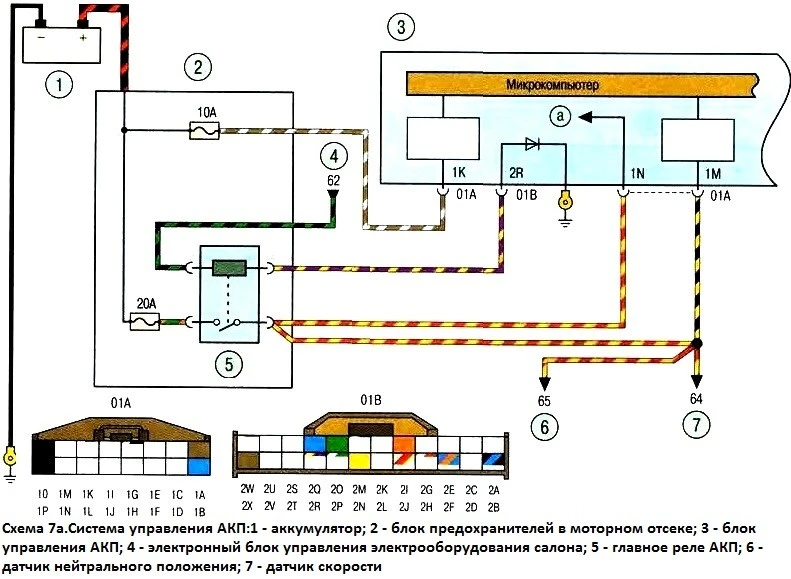
Scheme 7a. Automatic transmission control system
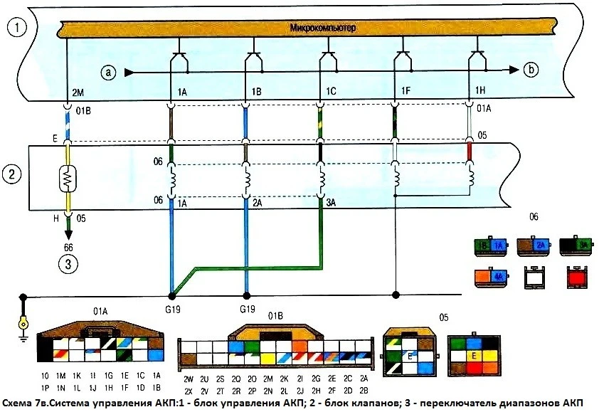
Scheme 7b. Automatic transmission control system
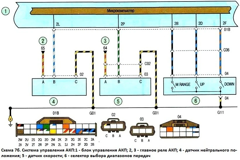
Scheme 7c. Automatic transmission control system
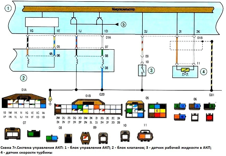
Scheme 7g. Automatic transmission control system
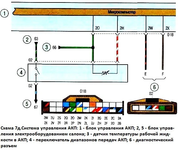
Scheme 7d. Automatic transmission control system
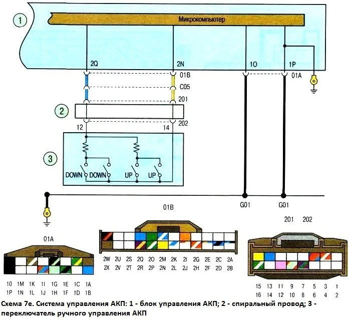
Scheme 7e. Automatic transmission control system
Looking for a short circuit
One of the methods for finding a short circuit is to remove the fuse and connect a probe lamp or voltmeter instead. There must be no voltage in the circuit
Pull the wiring while watching the probe lamp. If the lamp starts flashing, there is a short to ground somewhere in this wiring harness, possibly caused by chafing of the wire insulation
A similar test can be carried out for each of the components of the electrical circuit by turning on the appropriate switches.
Checking the reliability of contact with the "ground"
Disconnect the battery and connect one of the wires of the test lamp, which has an independent power source, to a point with known good contact with ground
Connect the other lamp wire to the wire harness or connector pin you are testing. If the lamp lights up, ground contact is OK (and vice versa).
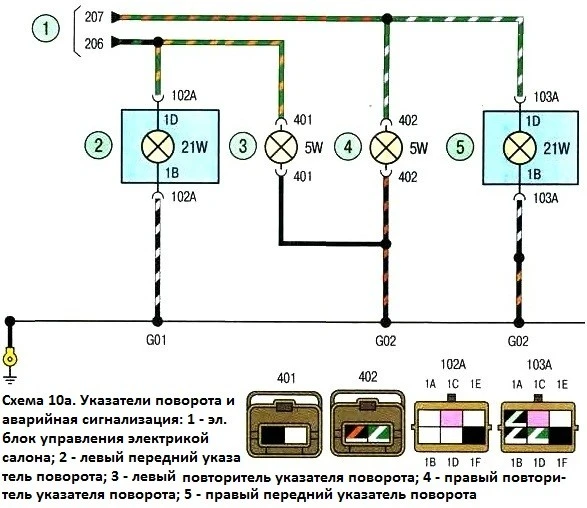
Scheme 19a. Direction indicators and hazard warning
An continuity test is performed to detect open circuits.
After disconnecting power to the circuit, test it with a self-powered test lamp.
Connect the probe wires to both ends of the circuit.
If the test lamp comes on, there is no open circuit. If the lamp does not light up, then this indicates an open circuit in the circuit.
Similarly, you can check the health of the switch by connecting the probe to its contacts.
When the switch is turned to the "ON" position, the probe lamp should light up.
Localization of the breakpoint
When diagnosing an open section of an electrical circuit, it is quite difficult to visually detect the cause of the malfunction, since it can be difficult to visually check the terminals for corrosion or a deterioration in the quality of their contacts due to limited access to them (usually the terminals are closed by the contact connector housing) .
A sharp twitch of the body of the wiring harness block on the sensor or the wiring harness itself in many cases leads to contact restoration
Keep this in mind when trying to isolate the cause of a circuit failure that is suspected to be an open circuit
Unstable failures may be due to oxidation of the terminals or poor quality of the contacts.
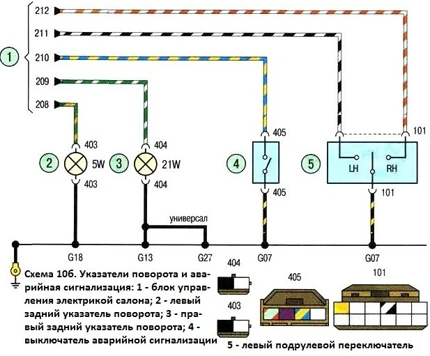
Scheme 10b. Direction indicators and hazard warning
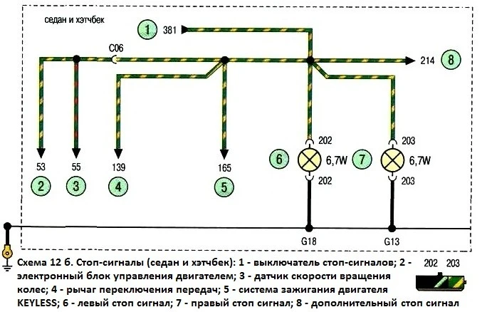
Scheme 12b. Stop lights (sedan and hatchback)
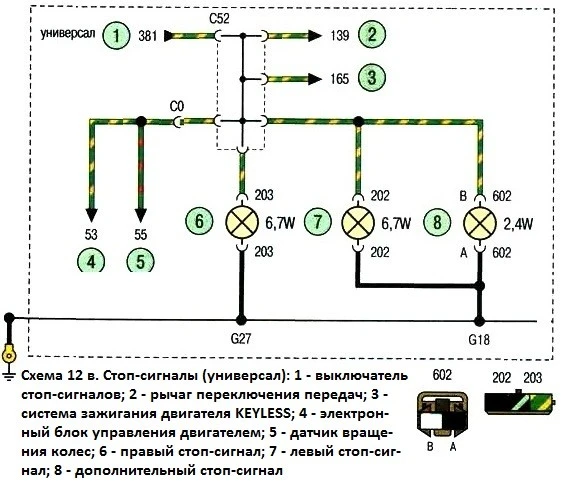
Scheme 12v. Brake lights (station wagon)
Scheme 12y. Brake lights (sedan and hatchback)
Diagnosing faults in electrical circuits is not a difficult task, provided it is clear that electric current is supplied to all consumers (lamp, electric motor, etc.) from the battery through wires through switches, relays, fuses, fuses, and then returns to the battery through the "mass" (body) of the car.
Any problems related to the failure of electrical equipment can be caused by the interruption of the supply of electricity to them from the battery or the return of current to the battery.

")
")
")
")
")
")
")
")