
Nissan Almera has been equipped with a JH3 manual transmission since 2013.
The gearbox is made according to a two-shaft scheme with five forward gears and one reverse gear, with synchronizers in all forward gears.
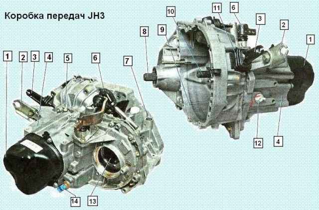
It is structurally integrated with the differential and final drive.
The gearbox housing consists of three parts: the clutch housing, the gearbox housing and the rear gearbox housing cover.
The clutch housing and gearbox housing are cast aluminum alloy, and the rear cover is stamped steel.
The clutch housing is attached to the gearbox housing with screws.
When assembling, a gasoline-oil-resistant sealant-gasket is applied between the crankcases.
The rear cover is attached to the crankcase with three bolts.
The input shaft is made as a block of drive gears, which are in constant engagement with the driven gears of all forward gears.
The gears of all forward gears are helical, and the reverse gears are spur gears.
Gears of 1-4 gears are made integral with the input shaft, the gear of the fifth gear rotates freely on the shaft.
A fifth gear synchronizer is installed at the rear end of the input shaft.
The secondary shaft is hollow, oil is supplied through it under the driven gears.
On the shaft there are driven gears and synchronizers of 1-2 and 3-4 gears.
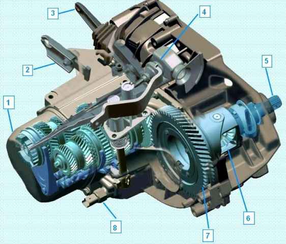
The fifth gear is splined on the shaft.
On the side of the clutch housing, the output shaft bearing is roller bearing, and on the side of the cover, it is ball bearing.
An oil sump is located under the roller bearing of the secondary shaft, directing the flow of oil into the shaft.
All parts mounted on the secondary shaft are pulled together in a package with a bolt screwed into the end of the shaft from the side of the cover.
The final drive gear is pressed onto the differential box.
Behind the driven gear, a tapered roller bearing is mounted on the differential case.
An adjusting ring is installed between the driven gear and the bearing, by selecting the thickness of which the preload in the differential bearings is adjusted.
On the other (right) side, a second tapered roller bearing is installed on the differential box.
The differential box has two satellites and two side gears.
The satellites are mounted on an axle fixed in the differential box.
The right side gear of the differential is made integral with the splined shaft, on which the inner joint of the right wheel drive is put on.
An oil seal pressed into the socket of the clutch housing works along the cylindrical surface of the shaft.
The left semi-axial gear is made on the body of the left wheel drive internal hinge, and the body is installed in the gearbox socket and secured in it with a retaining ring.
In order to prevent oil leakage from the gearbox, the connection of the inner joint of the left wheel drive with the gearbox housing is sealed with a rubber boot, which is attached to the gearbox housing with a metal holder.
The other side of the cover is attached to the outer ring of the needle bearing mounted on the left wheel drive shaft.
The needle bearing is integral with the oil seal, which prevents oil leakage from the gearbox along the wheel drive shaft.
To prevent water ingress and reduce dust ingress into the gearbox cavity, the saloon fitting is connected by a rubber hose with a plastic tip, placed in the upper part of the engine compartment.
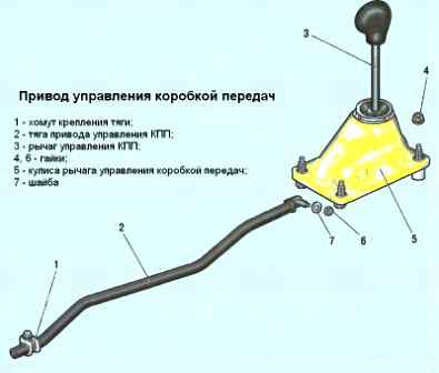
The gearbox control drive consists of a control mechanism, a control rod and a gear change mechanism.
A ball joint is installed on the gear lever, which is inserted into the plastic housing of the control mechanism and secured with a retainer.
A bushing is welded to the lower end of the lever, to which the control rod is attached.
The other end of the control rod is attached to the gearshift mechanism mounted on the gearbox.
At the factory, the gearbox is filled with gear oil designed for the entire life of the vehicle.
Gear ratios
|
Transfer |
Forward number |
|---|---|
|
I |
3,727 |
|
II |
2,043 |
|
III |
1,393 |
|
IV |
1,029 |
|
V |
0.795 |
|
Rear. move |
3,545 |
|
Home |
4,214 |

")
")
")
")
")
")
")
")