


Gearbox disassembly was covered in the article: «Gearbox disassembly».
After washing and inspecting the gearbox components, we proceed with assembly.
We have already installed the bearings and differential.
Install the output shaft assembly, the first/second gear selector fork and the input shaft simultaneously (Fig. 1).
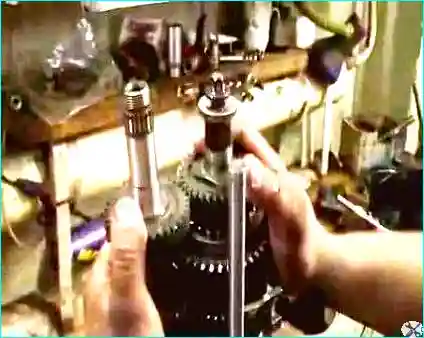
Fig. 1. Install the output shaft assembly, the first/second gear selector fork and the input shaft simultaneously
Install the detent plungers (bosses) into their bores (Fig. 2).
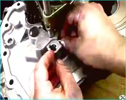
Fig. 2. Install the detent plungers (bosses) into their bores
Install the third/fourth gear selector fork (Fig. 3).
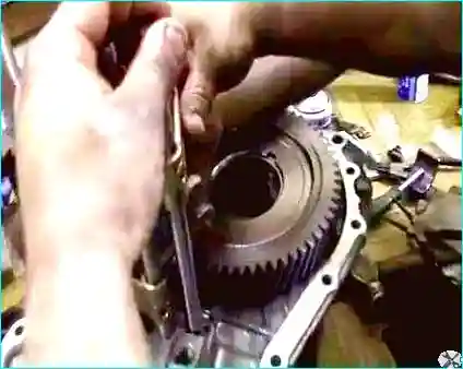
Fig. 3. Install the third/fourth gear selector fork
Drive the pin into the third/fourth gear selector fork with a hammer (Fig. 4).
All selector forks must be in the neutral position, i.e. no gear engaged.
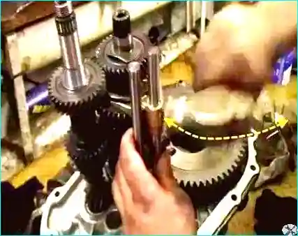
Fig. 4. Drive the detent of the third/fourth gear selector fork
Install the reverse gear synchroniser sleeve (Fig. 5).
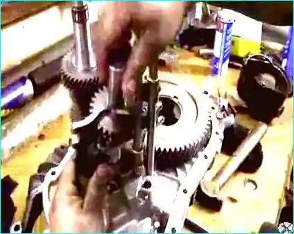
Fig. 5. Install the reverse gear synchroniser sleeve
Insert the fifth gear selector fork guide (Fig. 6).
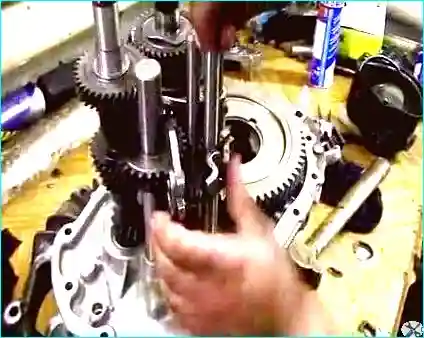
Fig. 6. Insert the fifth gear selector fork guide
Drive the locking pin of the reverse gear synchroniser sleeve (Fig. 7).
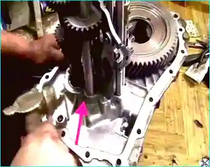
Fig. 7. Drive the locking pin of the reverse gear synchroniser sleeve
Before installing the gearbox housing, third gear must be engaged (Fig. 8).
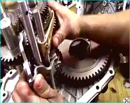
Fig. 8. Before installing the gearbox housing, third gear must be engaged
This is necessary so that the selector finger located in the housing (Fig. 9) engages with the third gear fork (Fig. 10).
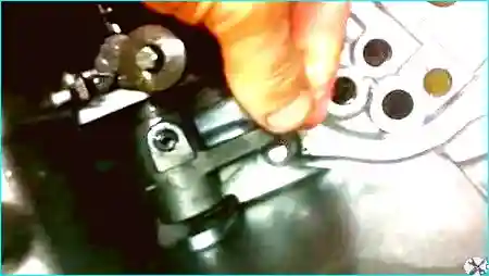
Fig. 9. Selector finger located in the housing
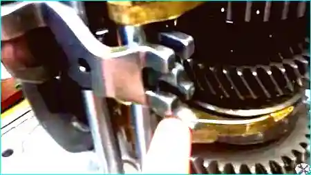
Fig. 10. Third gear selector fork
Apply sealant to the joint face of the housing (Fig. 11).
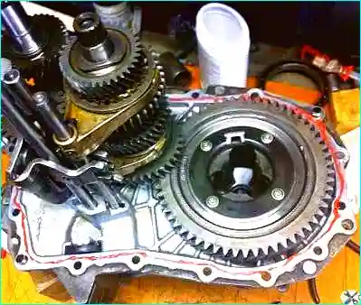
Fig. 11. Apply sealant to the joint face of the housing
Place the magnet into the special pocket in the gearbox housing (Fig. 12).
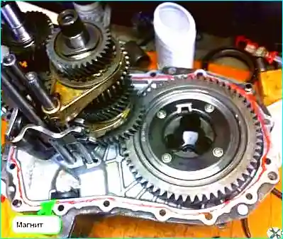
Fig. 12. Place the magnet into the special pocket in the gearbox housing
Insert the oil trough into the gearbox housing (Fig. 13).
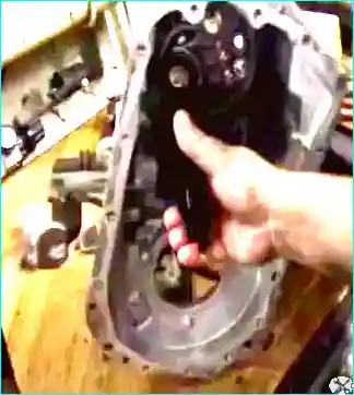
Fig. 13. Insert the oil trough into the gearbox housing
Move the lever to the third gear position and begin installing the gearbox housing (Fig. 14).
(This operation is carried out by two people.) At the start of housing installation, the fifth gear selector rod comes out first.
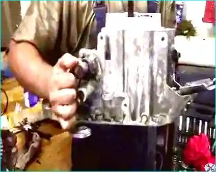
Fig. 14. Move the lever to the third gear position and begin installing the gearbox housing
Before it comes out, insert the detent spring and ball and hold them in place (Fig. 15).
The assistant meanwhile lowers the housing slightly. The rod comes out through the housing opening and the detent remains in place.
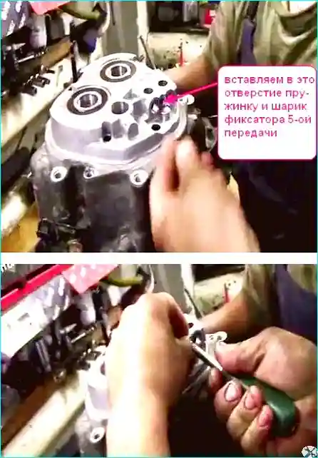
Fig. 15. Before the rod comes out, insert the detent spring and ball and hold them in place
In the same way, insert the detents and the first/second gear selector rod (Fig. 16).
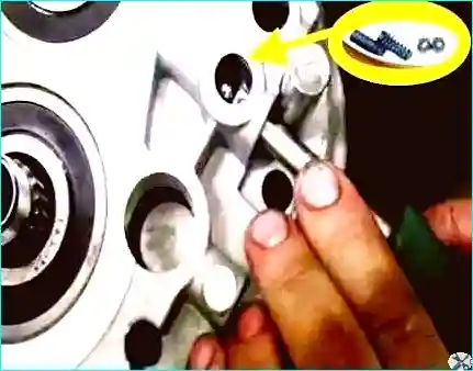
Fig. 16. In the same way, insert the detents and the first/second gear selector rod
Next, insert the detent and the third/fourth gear selector rod (Fig. 17).
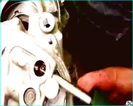
Fig. 17. Insert the detent and the third/fourth gear selector rod
After joining the housing halves, check that the gears can be engaged.
If all gears can be engaged, the assembly was correct.
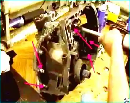
Fig. 18. Start and tighten the 16 gearbox housing bolts
Before final tightening of the bolts, the input shaft must be turned to allow the bearings to self-align.
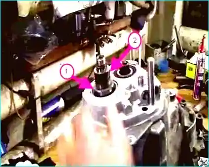
Fig. 19. Before final tightening of the bolts, the input shaft must be turned to allow the bearings to self-align
Install the thrust washer on the input shaft (correct position of the sleeve is shown in Figure 8 of the gearbox disassembly article) and the gear sleeve (Fig. 20).
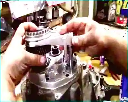
Fig. 20. Install the thrust washer and gear sleeve on the input shaft
Install the fifth gear gearwheel with the synchroniser and selector fork (Fig. 21).
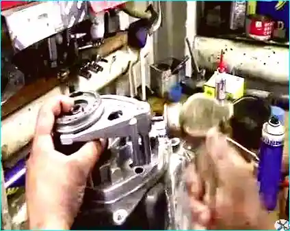
Fig. 21. Install the fifth gear gearwheel with the synchroniser and selector fork
Drive the pin into the fifth gear selector fork with a hammer (Fig. 22).
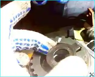
Fig. 22. Drive the pin into the fifth gear selector fork with a hammer
Install the locking washer (Fig. 23).
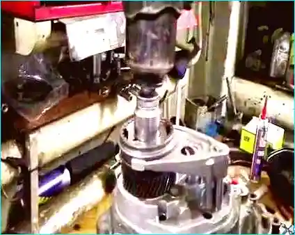
Fig. 23. Install the locking washer
Start and tighten the nut on the rear end of the input shaft (Fig. 24) (tighten it to 190 N·m).
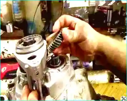
Fig. 24. Start and tighten the nut on the rear end of the input shaft (190 N·m)
Install the fifth gear driven gearwheel on the output shaft (Fig. 25).
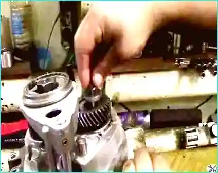
Fig. 25. Install the fifth gear driven gearwheel on the output shaft
Start and tighten the bolt on the rear end of the output shaft (Fig. 26) (tightening torque 70 N·m).
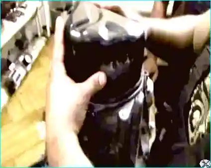
Fig. 26. Start and tighten the bolt on the rear end of the output shaft (70 N·m)
Install a new O-ring and install the rear cover of the gearbox housing (Fig. 27).
Tighten the three rear cover bolts.

Fig. 27. Install a new O-ring and install the rear cover of the gearbox housing
Torque specifications for gearbox components:
- Filler plug: 3 N·m;
- Gearbox housing to clutch housing bolts: 25 N·m;
- Output shaft rear end bolt: 70 N·m;
- Input shaft rear end nut: 190 N·m;
- Rear cover bolts: 25 N·m;
- Reverse light switch: 25 N·m;
- Clutch slave cylinder bolt: 21 N·m;
- Selector shaft bolt: 20 N·m;
- Selector finger bolt: 10 N·m;
- Reverse gear fork rod bracket bolt: 25 N·m;
- Drain plug: 25 N·m;
- Selector shaft detent: 21–23 N·m;
- Gearbox housing to clutch housing bolts with Loctite: 63 N·m;
- Remaining gearbox housing to clutch housing bolts: 52 N·m;
- Final drive driven gearwheel bolts: 120 N·m;
- Reverse gear fork bracket bolts: 15 N·m.


