


Checking and adjusting the wheel alignment angles are necessary to ensure good vehicle stability and handling, as well as even tyre wear during operation.
Wheel alignment angles are checked and adjusted on special alignment rigs according to their operating instructions.
The discrepancy between the actual values measured on the vehicle and the reference values given in the tables is due to wear or deformation of suspension components or deformation of the body.
The values given in the table are valid for vehicles with a full fuel tank and a load of 70 kg on each front seat.
After placing the vehicle on the alignment rig (immediately before checking the angles), «settle» the vehicle suspension by applying a force of 392–490 N (40–50 kgf) two or three times from top to bottom, first to the rear bumper and then to the front bumper.
The vehicle's wheels must be parallel to the vehicle's longitudinal axis.
When checking and adjusting the front wheel alignment angles, first check the castor angle, then the camber angle, and finally the toe-in.
After adjusting the wheel alignment angles, perform the programming of the torque and steering wheel angle sensor using a diagnostic tool.
Wheel alignment angle table
- Front wheel camber: 0°02′ ± 30′, maximum difference between left and right wheels — 0°30′;
- Front wheel toe-in: 1.2 mm, maximum difference between left and right wheels — 1.2 mm;
- Front wheel castor: 5°20′ ± 30′, maximum difference between left and right wheels — 0°30′;
- Rear wheel camber: -1°30′ ± 20′, maximum difference between left and right wheels — 0°20′;
- Rear wheel toe-in: 1.2 mm, maximum difference between left and right wheels — 1.2 mm.
Castor angle
The front wheel castor angle is formed by the vertical line and the line passing through the centre of the upper mount of the MacPherson strut and the centre of the ball joint sphere secured to the lower suspension arm.
Adjustment of the castor angle is not provided for by the vehicle design.
If the angle deviates from the nominal value, replace the damaged or deformed components.
Maximum difference between right and left wheels = 30′.
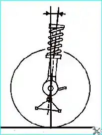
Fig. 1. Castor angle
Values - Front suspension position, mm:
- 4°30′ ± 30′ — W2-W1 = 94;
- 5°06′ ± 30′ — W2-W1 = 75;
- 5°42′ ± 30′ — W2-W1 = 62;
- 6°18′ ± 30′ — W2-W1 = 46.
Camber angle
The front wheel camber angle is the deviation of the wheel's plane of rotation from the vertical.
Adjustment of the front wheel camber angle is not provided for by the vehicle design.
Maximum difference between right and left wheels = 30′.
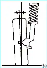
Fig. 2. Camber angle
Values - Front suspension position, mm:
- 0°30′ ± 30′ — R1-W1 = 118;
- -0°01′ ± 30′ — R1-W1 = 125;
- -0°12′ ± 30′ — R1-W1 = 146;
- -0°16′ ± 30′ — R1-W1 = 158.
Toe-in
It is adjusted by rotating the tie rod sleeves.
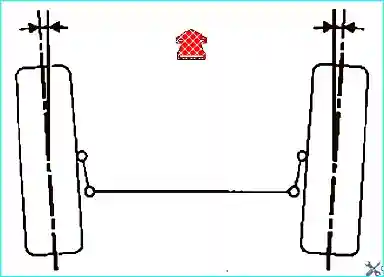
Fig. 3. Toe-in
Values - Front suspension position, mm:
- For two wheels (toe-out): 0°10″ ± 10″ — unladen vehicle;
- For 15″ wheels: 1.1 mm ± 1.1 mm;
- For 16″ wheels: 1.2 mm ± 1.2 mm;
- For 17″ wheels: 1.3 mm ± 1.3 mm.


