


Fuel tank construction
Purpose of the valves and the filler neck
Overpressure/vacuum safety valve
If the petrol vapour recirculation circuit is blocked, this valve prevents overpressure (tank swelling) or vacuum (tank collapsing due to fuel consumption) from occurring in the tank.
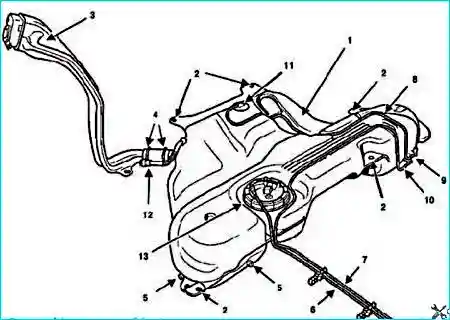
Fig. 1. Fuel tank: 1 - fuel tank, 2 - mounting holes, 3 - filler neck, 4 - filler neck retaining clamp, 5 - brake pipe mounting brackets, 6 - fuel supply pipe, 7 - petrol vapour supply pipe; 8 - petrol vapour return pipe to the carbon canister (from the fuel tank), 9 - atmospheric vent, 10 - carbon canister, 11 - anti-spill valve and roll-over valve, 12 - anti-surge tube (degassing during filling), 13 - fuel pump with level sensor assembly
Restrictor valve
This valve prevents the introduction of a leaded petrol or diesel fuel nozzle into the filler neck.
Anti-spill valve and roll-over valve.
The operating element of the anti-spill valve is a ball.
When the vehicle is stationary during refuelling, the ball rests on its seat, thereby blocking a certain volume of air in the tank.
When the vehicle is moving, the ball lifts off its seat, opening communication between the tank and the carbon canister.
A certain volume of air must always be present in a tank full of fuel.
This allows the fuel to expand without causing the tank to swell.
The roll-over valve prevents the tank from emptying through the line to the carbon canister.
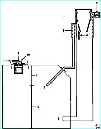
Fig. 2. Fuel system operation diagram: 1 - connection for pipe to carbon canister; 2 - ball-type anti-spill valve; 3 - anti-surge tube during filling; 4 - restrictor valve; 5 - overpressure/vacuum safety valve; 6 - air release hole during refuelling; 7 - fuel expansion chamber; 8 - filler hole; 9 - usable fuel volume; 10 - anti-spill valve and roll-over valve
Filler neck
The unleaded petrol filler neck has:
- a smaller diameter filler opening than a standard fuel nozzle (restrictor valve).
Use of leaded petrol damages the exhaust emission control system:
- oxygen sensor and catalytic converter;
- valve that closes the filler opening to prevent petrol vapour emissions or fuel spillage;
- sealing cap.
Removing and installing the fuel tank on a Renault Megane 2
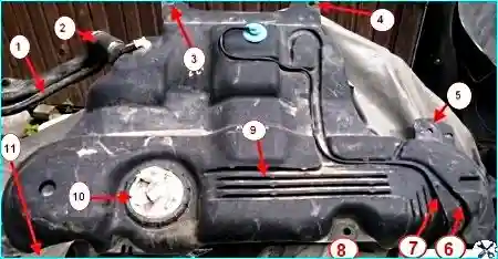
Fig. 3. Fuel tank: 1 - breather hose, 2 - filler neck hose, 3 - rear bracket, 4,5 - heat shield mounting brackets, 6 - carbon canister hose, 7 - supply hose to carbon canister, 8 - left bracket, 9 - fuel tank, 10 - fuel module, 11 - right fuel tank mounting bracket
The fuel tank is removed if a leak is found or if it needs to be cleaned.
It is easier to remove an empty fuel tank.
If, of course, there is a lot of fuel in the tank, it should be pumped out through the fuel module mounting hole.
Before removing the tank, relieve the pressure in the fuel system.
Disconnect the negative battery terminal.
Disconnect the wiring harness connector and fuel lines from the fuel module.
Remove the rear suspension beam (it is possible to leave the beam in place, but this will make the job more difficult).
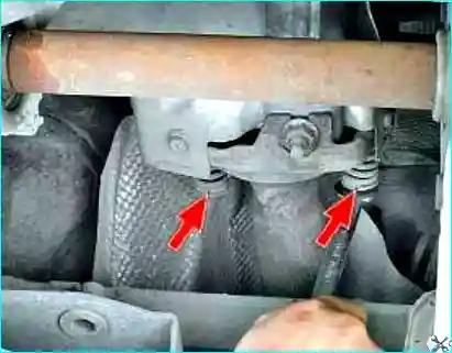
Fig. 4. Unscrew the bolts securing the catalytic converter pipe to the exhaust manifold

Fig. 5. Remove the bolts with their springs
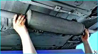
Fig. 6. Disconnect the silencer from its mounts and remove the assembly
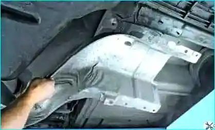
Fig. 7. Remove the heat shield from the additional silencer pipe
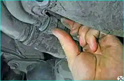
Fig. 8. Release the fuel tank breather hose clip
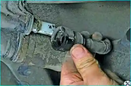
Fig. 9. Disconnect the hose from the filler pipe
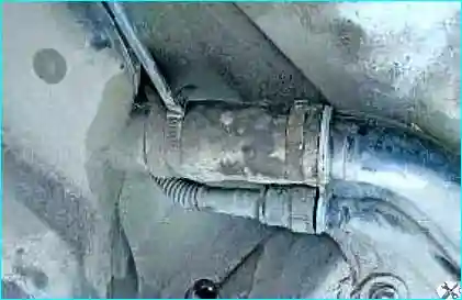
Fig. 10. Spread the tabs of the filler hose clip retainers
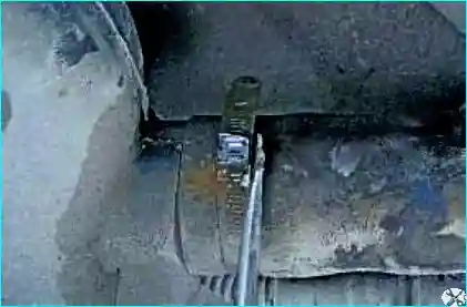
Fig. 11. Bend the upper part of the clip retainer
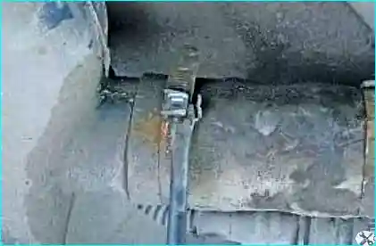
Fig. 12. Bend the lower part of the clip retainer
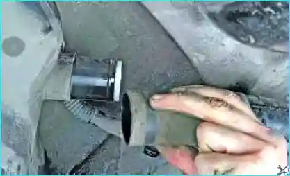
Fig. 13. Open the clip and disconnect the hose from the fuel tank connection
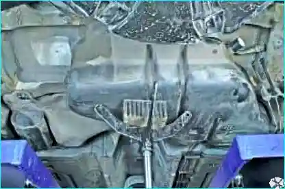
Fig. 14. Support the fuel tank
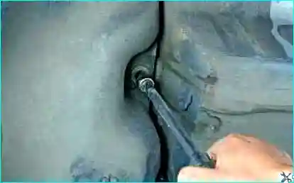
Fig. 15. Unscrew the left fuel tank mounting bolt
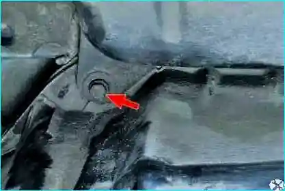
Fig. 16. Unscrew the rear mounting bolt
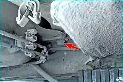
Fig. 17. Unscrew the front fuel tank mounting bolt
Remove the fuel tank.
Take care not to damage the brake pipes or the parking brake cable during removal.
Installation
Straighten the heat shield.
Ensure that the heat shield does not touch the fuel tank.
The fuel tank hose clips must always be replaced with new ones.
Installation is carried out in the reverse order of removal.
Tighten to the specified torque:
- the wheel bolts (110 N·m);
- the fuel tank mounting bolts (21 N·m).
Check that the fuel lines are securely fastened.
Install the fuel module.
Connect the cables to the battery terminals, starting with the positive terminal.


