


Removing the valve springs
To correctly compress the valve springs, the plunger of the tool (Mot1502) must be centred over the valve stem.
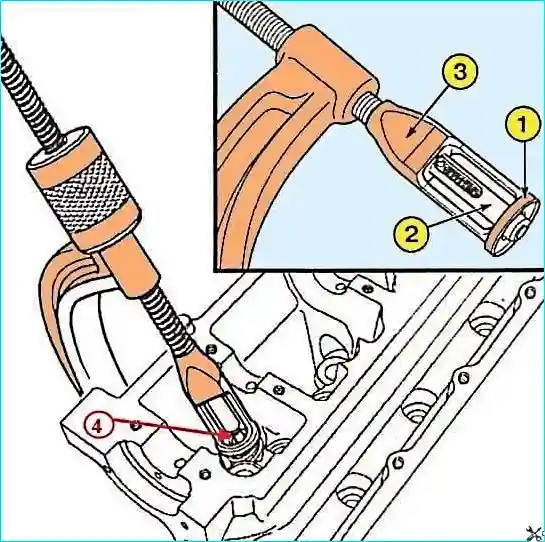
Fig. 1. Removing the valves using tool Mot1502: 1 - bore, 2 - plunger, 3 - pressure sleeve, 4 - valve stem
The valve spring cap must engage in the bore of the pressure sleeve of the tool (Mot1502) (Fig. 1).
Remove:
- the collets;
- the valve spring caps;
- the valve springs;
- the valves;
- the valve stem seals using pliers (Mot1335).
Checking the cylinder head height
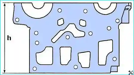
Fig. 2. Measuring the cylinder head height
Measure the height of the cylinder head (Fig. 2).
The cylinder head height is 137 mm.
Checking the cylinder head for leaks
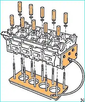
Fig. 3. Tool for checking cylinder head leakage
Check the cylinder head for cracks using a special tool (Fig. 3).
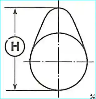
Fig. 4. Measuring the cam height of the camshaft
Measure the cam height (Fig. 4).
Cam height:
- inlet: 40.661 ± 0.03 mm;
- exhaust: 40.038 ± 0.03 mm.
Checking the diameters of the camshaft journals and bearing bores
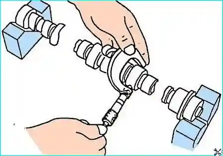
Fig. 5. Measuring the diameter of the camshaft journals
Measure the diameter of the camshaft journals (Fig. 5).
Camshaft journal diameter:
- journals No. 1, 2, 3, 4, 5 – 24.979–25.000 mm;
- journal No. 6 – 27.979–28.000 mm.
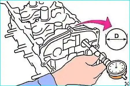
Fig. 6. Measuring the diameter of the camshaft bearing bores
Measure the diameter of each camshaft bearing bore (Fig. 6).
Camshaft bearing bore diameter:
- journals No. 1, 2, 3, 4, 5 – 25.040–25.061 mm;
- journal No. 6 – 28.040–28.061 mm.
Checking the camshaft end float
Install the camshafts, ensuring they are in the correct position, and the cylinder head cover.
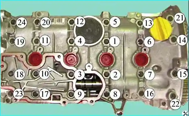
Fig. 7. Tightening sequence for the cylinder head cover bolts of the K4M engine
Tighten in the order shown in Figure 7 to the specified torque:
- cylinder head bolts 13–20–22–23 (8 N·m);
- cylinder head cover bolts 1–12, 14–19 and 21–24 (15 N·m).
Loosen the cylinder head cover bolts 13–20–22–23.
Tighten in the specified order to the specified torque the cylinder head cover bolts 13–20–22–23 (15 N·m).
Secure the magnetic stand to the cylinder head using the mounting plate of the tool (Mot588), tightening it with the oil separator bolts and spacer sleeves having the following dimensions:
- outer diameter 18 mm;
- diameter of the bolt hole 89 mm;
- height 15 mm.
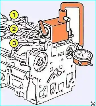
Fig. 8. Installing the magnetic stand on the cylinder head: 1 – mounting plate; 2 – spacer sleeves; 3 – bolts
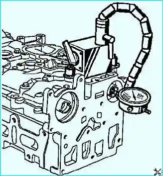
Fig. 9. Checking the end float
Check the end float, which must be between 0.08 and 0.178 mm (Fig. 9).
Remove the cylinder head cover and the camshafts.
Checking the valves
Inlet valves: Х1 = 75.14 ± 0.35 mm, D = 5.470–5.485 mm.
Exhaust valves: Х1 = 77.5 ± 0.35 mm, D = 5.456–5.471 mm.
Valve head diameter D:
- inlet valves – 32.7 ± 0.12 mm;
- exhaust valves – 27.96 ± 0.12 mm.
Valve length L:
- inlet valves – 109.32 mm;
- exhaust valves – 107.64 mm.
Valve seat angle A:
- inlet – 45°45′;
- exhaust valves – 45°.
Head thickness T:
- inlet valves – 1.15 mm;
- exhaust valves – 1.27 mm.
Valve lift:
- inlet valves – 9.221 mm;
- exhaust valves – 8.075 mm.
Checking the clearance between the valve stems and guides

The clearance between the valve stem and guide can be checked in two ways.
First method
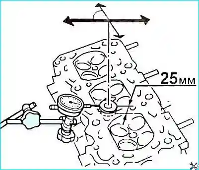
Fig. 10. Checking the clearance of the valve stem in the guide
Lift the valve head by 25 mm, then use a dial gauge to measure the valve movement in the direction of the arrows at 90° to the camshaft axis.
Half of the value obtained is equal to the clearance between the valve stem and guide (Fig. 10).
Second method
Measure the diameter of the valve stem and the inside diameter of the guide.
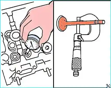
Fig. 11. Checking the clearance between the valve stem and guide
The clearance between the guide and the valve stem is calculated by subtracting the two measured diameters (Fig. 11).
Nominal clearance:
- for inlet valves – 0.015–0.048 mm;
- for exhaust valves – 0.029–0.062 mm.
Checking the valve springs
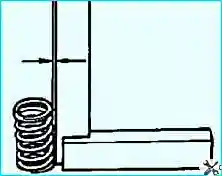
Fig. 12. Checking the valve springs
Check the spring deviation from the vertical, which must not exceed 1.2 mm (Fig. 12).
Check the spring calibration.
Spring length under load:
- under a load of 18–20 N, the spring length is 34.50 mm;
- under a load of 56.3–61.7 N, the spring length is 24.50 mm.
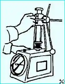
Fig. 13. Checking the spring calibration
- free length of the spring 41.30 mm (Fig. 13).
Assembling the cylinder head
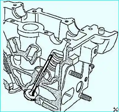
Fig. 14. Insert the valve into the cylinder head
Fit the tool sleeve (Mot. 1511) onto the valve stem (the internal diameter of the sleeve must match the stem diameter).
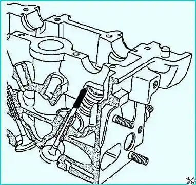
Fig. 15. Hold the valve pressed against its seat
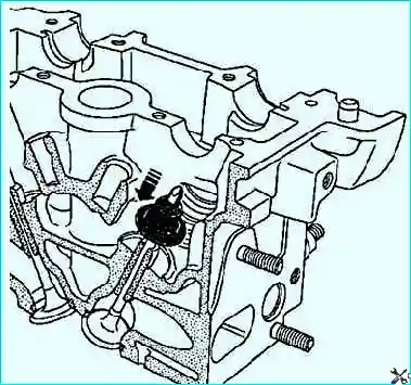
Fig. 16. Fit the valve stem seal (lubricated with oil) onto the sleeve
Push the valve stem seal until it passes over the sleeve (Fig. 17).
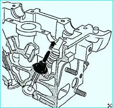
Fig. 17. Remove the sleeve
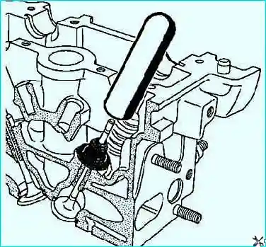
Fig. 18. Fit the driver over the valve stem seal
The internal diameter of the driver must match the diameter of the valve stem.
In addition, the lower part of the driver must partially rest on the valve stem seal, which serves as the support washer for the valve spring.
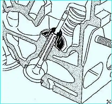
Fig. 19. Press the valve stem seal on by tapping the top of the driver with the palm of your hand until the valve stem seal contacts the cylinder head
Repeat for all valves.
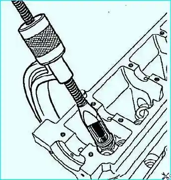
Fig. 20. Install the springs and spring caps
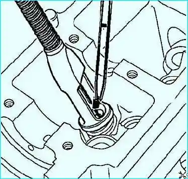
Fig. 21. Insert the collets using bent pliers
Install the thermostat housing with a new gasket onto the cylinder head.
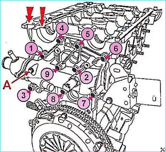
Fig. 22. Tightening sequence for the thermostat bolts: A - bleed connection
Tighten in the order shown in Figure 22 to the specified torque (10 N·m) the bolts securing the thermostat housing to the cylinder head.
Install the exhaust manifold with a new gasket.
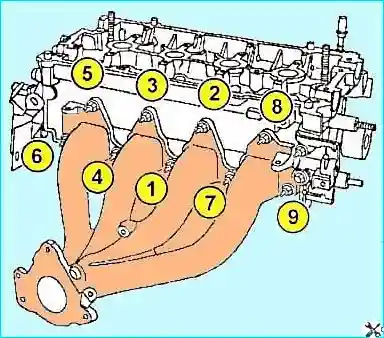
Fig. 23. Tightening sequence for the nuts on the exhaust manifold studs
Tighten in the order shown in Figure 23 to the specified torque (23 N·m) the nuts on the exhaust manifold studs.
Install the exhaust manifold heat shield.
Tighten the exhaust manifold heat shield bolts to the specified torque.
Ensure that the exhaust manifold heat shield is securely retained between the oxygen sensor and the manifold (to avoid overheating which could damage the wiring of the upstream oxygen sensor).
Tighten the oxygen sensor to the specified torque (4.5 N·m) using the tool (Mot1495).
Install the spacer for the timing cover inner casing.
Install the injector housing support plates with a new gasket. Install the oxygen sensor.
Align the injector housing support plate with respect to the cylinder head (on the timing side) (Fig. 24).
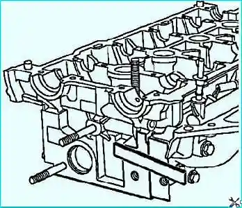
Fig. 24. Align the mating surfaces of the injector housing support plate with respect to the cylinder head
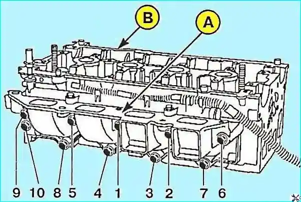
Fig. 25. Tightening sequence for the lower intake manifold bolts
Tighten in the specified order to the specified torque (21 N·m) the bolts securing the injector housing gasket (Fig. 25).


