


General structure of the crankcase ventilation system
The location of the elements of the crankcase ventilation system (K4J engine) is shown in Fig. 1.
Operating principle:
- At low loads, oil vapours are drawn in in small quantities through a calibrated orifice.
- At medium and high loads, oil vapours are drawn in in large quantities through the throttle body.
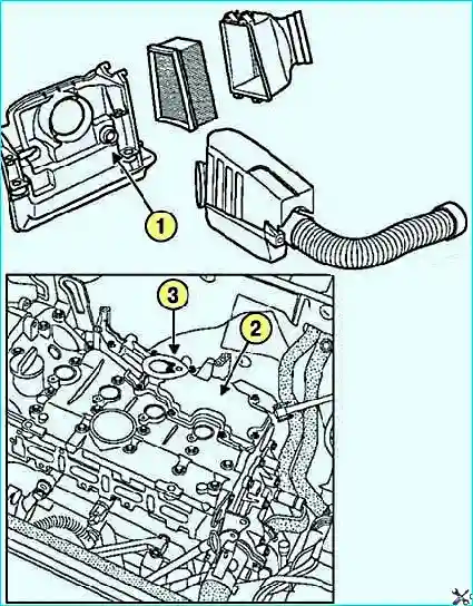
1 — inlet opening of the crankcase ventilation system;
2 — oil deflector of the ventilation system on the cylinder head cover;
3 — calibrated orifice
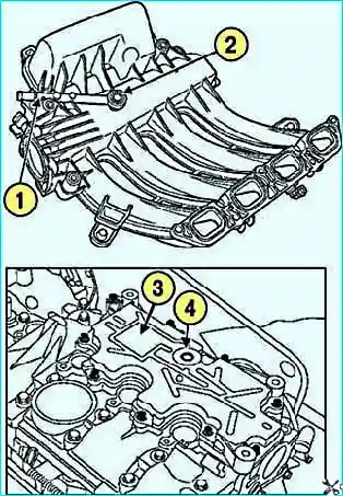
1 — crankcase ventilation pipeline;
2 — calibrated orifice;
3 — oil separator of the crankcase ventilation system on the cylinder head cover;
4 — inlet opening of the crankcase ventilation system
Important! To ensure the normal operation of the exhaust gas emission reduction system, the crankcase ventilation system must be kept clean and in good condition.
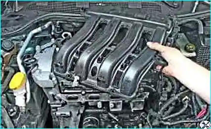
Cleaning the ventilation system
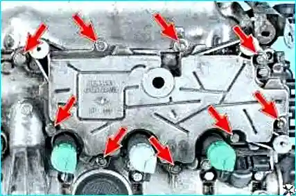
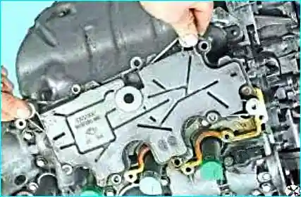
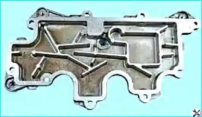
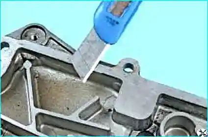
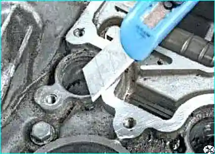
Refitting: we apply a special sealant to the mating surfaces of the cylinder head cover and the oil separator.
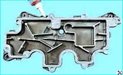
We refit all parts in the reverse order.
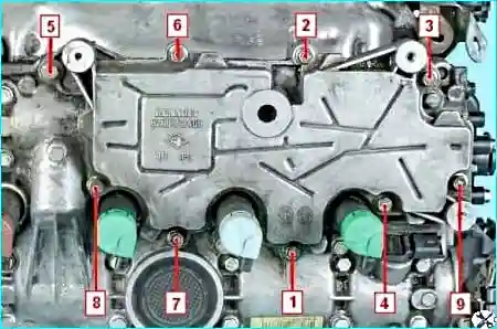
Tightening torque: we tighten the oil separator securing bolts to a torque of 13 N·m in the sequence shown in Fig. 10.
Recommendation: after cleaning the crankcase ventilation system, it is recommended to check the engine operation at idling and under various loads to make sure there is no air leak and that the ventilation is normal.


