


General structure of the fuel vapour recovery system
The fuel vapour recovery system prevents the escape into the atmosphere, from the fuel system, of fuel vapours that adversely affect the ecology of the environment.
The system uses the method of absorbing the vapours by a carbon canister, which is installed on the fuel tank under the vehicle (it may be installed in the luggage compartment, depending on equipment).
Operating principle: the electromagnetic purge valve, on the signals of the engine control unit, switches the operating modes of the system. Fuel vapours from the fuel tank are constantly led off through a pipeline and accumulate in the canister filled with activated carbon (adsorbent).
During engine operation, regeneration (restoration) of the adsorbent occurs by purging the canister with fresh air entering the system under the action of the vacuum transmitted through the pipeline from the receiver into the canister cavity when the purge valve opens.
The control unit regulates the degree of canister purging depending on the engine operating mode, sending to the valve a signal with a variable pulse frequency. The fuel vapours from the canister pass through the pipeline into the engine receiver and burn in the cylinders.
Signs of a fault: faults in the fuel vapour recovery system entail unstable idling, engine stalling, increased toxicity of the exhaust gases and deterioration of the vehicle's driving qualities.
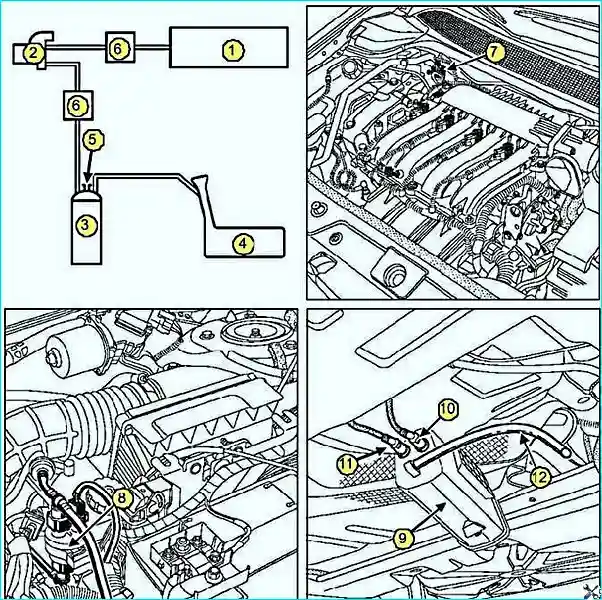
1 — intake manifold; 2 — electromagnetic canister purge valve; 3 — canister; 4 — fuel tank;
5 — atmospheric connection opening; 6 — non-return valve (only on the F4R 776 engine);
7 — K4M canister purge electromagnetic valve; 8 — canister purge electromagnetic valve (F4R);
9 — canister; 10 — pipeline for supplying petrol vapours from the fuel tank;
11 — pipeline for supplying petrol vapours to the intake manifold; 12 — canister atmospheric connection pipe
The connection of the fuel tank with the atmosphere is made through the canister (fuel vapour trap). The petrol vapours are retained by the activated carbon contained in the canister. The petrol vapours from the canister pass into the engine, where they burn.
For this, the canister is connected to the intake manifold by means of the electromagnetic valve, which is located on the splash guard cup.
Operating principle of the electromagnetic valve: change of the flow section depending on the signal of the cyclic opening degree coming from the injection system ECU. The change of the flow section of the channel for the fuel vapours occurs due to the balance between the magnetic field created by the winding supply voltage and the force of the return spring ensuring the closing of the electromagnetic valve.
Canister purging conditions
The control signal to the electromagnetic canister purge valve is sent through contact С-Е1 of the ECU connector under the following conditions:
- coolant temperature above 55 °C;
- air temperature above 10 °C;
- the engine is not in idling mode;
- the set load threshold has been reached;
- the throttle position sensor is not in the «idle» position.
Diagnostics: when carrying out diagnostics using the «on-board diagnostic system», canister purging is not permitted.
The cyclic opening degree of the electromagnetic canister purge valve can be determined using the diagnostic tool by reading parameter PR102 (cyclic opening degree of the electromagnetic canister purge valve). The electromagnetic valve is closed when the parameter value is below 1.2 %.
Removing and checking the canister
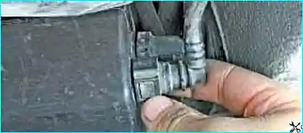
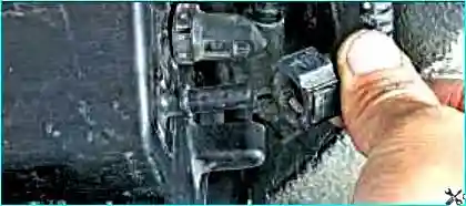
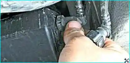
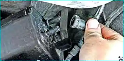
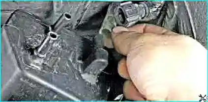
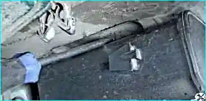
We prise up with a large screwdriver, overcoming the elastic resistance of the retainers, and remove the canister.
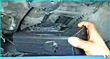
Refitting: we refit the canister in the reverse order.
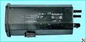
Checking the canister
- Plug on the canister the stub of the pipeline coming from the fuel tank.
- Connect the pressure gauge of the tool (Mot. 1311-01) to the atmospheric connection stub of the canister.
- During engine operation at idling, make sure that there is no vacuum in the atmospheric connection stub of the canister (and also that the value of the parameter «cyclic opening degree of the electromagnetic canister purge valve» read on the tool remains minimal: X ≤ 1.5 %).
If there is vacuum: with the ignition off, using a vacuum pump create a vacuum of 500 mbar at the outlet of the electromagnetic valve. The vacuum must not change by more than 10 mbar in 30 seconds.
- If the pressure changes — the electromagnetic valve is faulty, replace it.
- If the pressure does not change, while the purging conditions are met, the vacuum must increase (at the same time the value of the parameter on the diagnostic tool screen must increase). Under this condition an electrical fault occurs, therefore the circuit must be checked.
Removing the electromagnetic canister purge valve
Precautions: we disconnect the negative battery terminal.
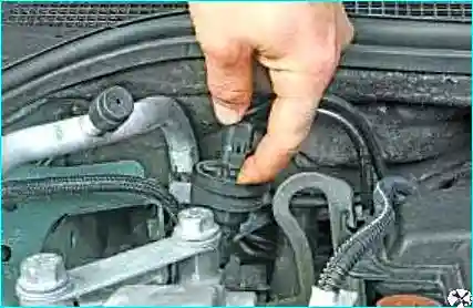
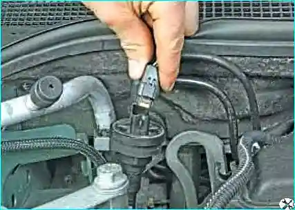
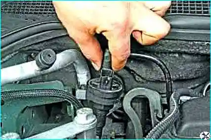
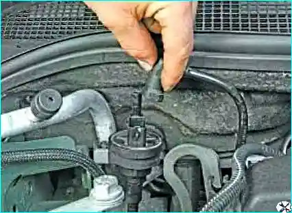
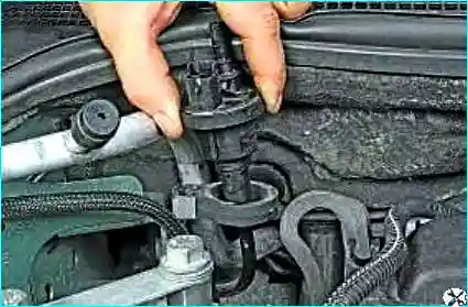
We take the valve out of the bracket.
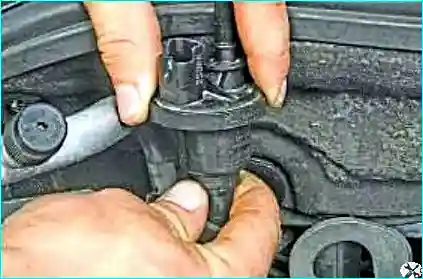
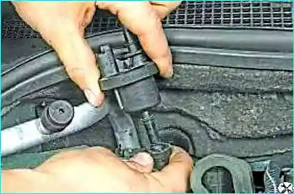
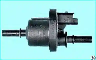
Refitting: we refit the canister electromagnetic valve in the reverse order.


