


General structure and operating principle of the phase regulator
To improve the filling of the cylinders with the fuel mixture in all modes, the 2.0 l engines are equipped with a phase regulator of the inlet valve camshaft.
The offset of the closing moment of the inlet valves optimises the filling of the cylinders with the fuel mixture depending on the crankshaft rotational speed. As a result, the torque in the medium load mode and the power at high crankshaft rotational speed are increased.
Operating principle:
- At high crankshaft rotational speed, a later closing of the inlet valves ensures the admission of an additional portion of the fuel mixture thanks to the high speed of movement of the mixture.
- At low rotational speed, the inertia of the mixture movement is small. Therefore an earlier closing of the exhaust valves is desirable in order to avoid insufficient filling of the cylinders and loss of torque due to the displacement of part of the fresh mixture.
- The higher the crankshaft rotational speed, the later the closing of the inlet valves must occur.
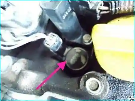
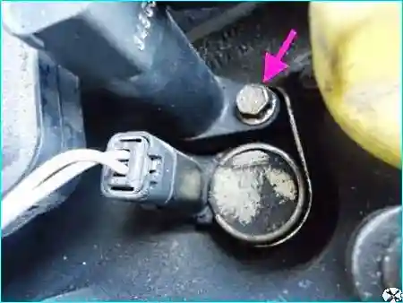
The phase regulator is either switched off or controlled by the injection system ECU through the electromagnetic valve installed on the cylinder head cover (see Fig. 2). The electromagnetic valve and the high-voltage coil are secured by a single bolt (Fig. 3).
Operating modes of the phase regulator
Control algorithm:
- At a crankshaft rotational speed within 1500–4300 rpm the ECU applies voltage to the electromagnetic valve.
- When 4300 rpm is exceeded, the supply to the electromagnetic valve is cut off.
- At a rotational speed up to 1500 rpm no voltage is applied to the electromagnetic valve. The mechanism is locked by the plunger.
When 4300 rpm is exceeded, the position of the phase regulator mechanism promotes the filling of the cylinders at high crankshaft rotational speed. In this position the locking plunger locks the mechanism.
From the moment the supply is applied to the electromagnetic valve at a crankshaft rotational speed of more than 1500 rpm, under the action of oil pressure the locking plunger withdraws and releases the mechanism.
Valve opening conditions: in the initial position the electromagnetic valve is closed. The valve opens the oil passage for controlling the phase regulator subject to the following conditions:
- the crankshaft rotational speed sensor is serviceable;
- the camshaft position sensors are serviceable;
- the injection system is serviceable;
- after the engine has started;
- the engine is not running at idle;
- the battery voltage is more than 11.4 V;
- the coolant temperature is above 30 °C;
- the engine is running within 1500–4300 rpm;
- the load is more than 87 % (approximately 900 mbar).
Signs of a fault: when the electromagnetic valve is locked in the open position, the engine runs unstably at idle, the pressure in the intake pipe is increased. At the same time a noisier engine operation is noted. The engine may even stall (there have been cases of engine failure).
Replacing the phase regulator
Preparatory work
Precautions: to replace the phase regulator we disconnect the negative battery terminal.
Sequence:
- We remove the plastic engine cover.
- We remove the throttle body (see the article on removing the throttle).
- We remove the right front wheel.
- We remove the right wing arch liner.
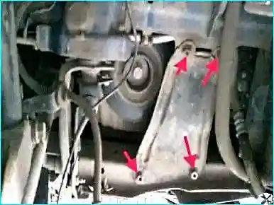
- We remove the lower engine guard.
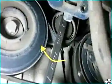
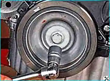
Removing the crankshaft pulley: we unscrew the bolt securing the auxiliary drive belt pulley. To unscrew the bolt, we lock the crankshaft against turning. We engage the highest gear in the manual gearbox and an assistant presses the brake pedal.
Removing the engine mounts
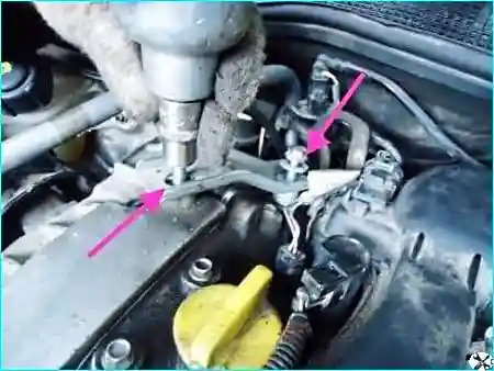
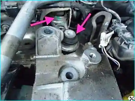
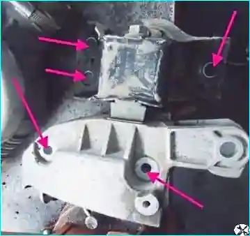
We unscrew two bolts securing the right rear power unit mount.
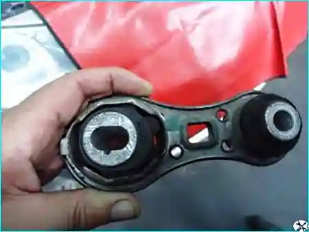
We unscrew the bolts securing the right front mount.
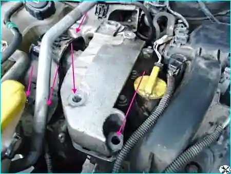
Withdrawing the front mount: by raising and lowering the engine, we withdraw the right front mount, trying not to damage the air conditioning pipe.
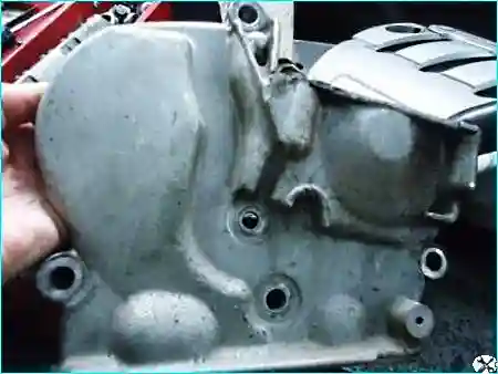
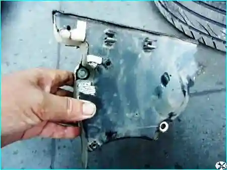
Removing the timing covers and preparing to set TDC
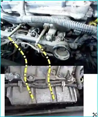
Removing the plugs: we pierce the camshaft service plugs and withdraw them.
Setting TDC
Important! In order not to disturb the valve timing, before removing the timing belt the crankshaft must be set to the TDC position of the first cylinder piston.
To turn the crankshaft we screw in the bolt securing the alternator belt pulley, having fitted a bush or a set of washers.
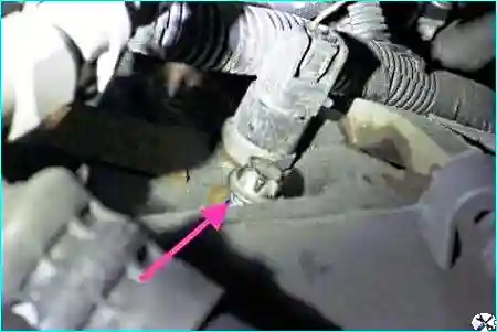
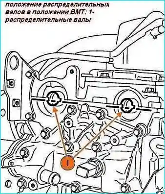
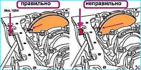
Turn the crankshaft slightly in the direction of working rotation so that the Mot.1054 retainer is located in the crankshaft locking slot.
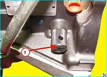
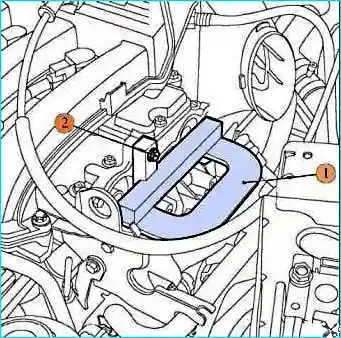
We insert the Mot.1496 tool into the slots of the camshafts.
Removing the phase regulator and the timing belt
Removing the phase regulator (two people with an assistant):
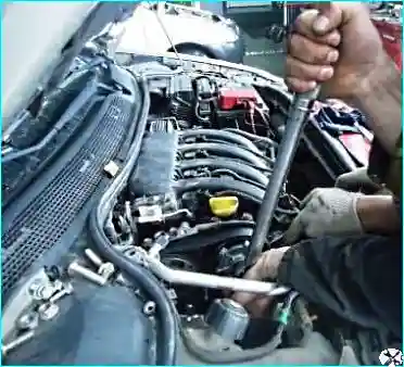
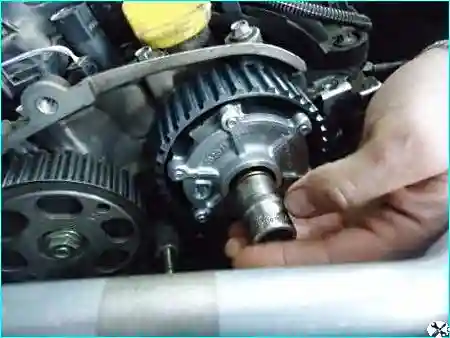
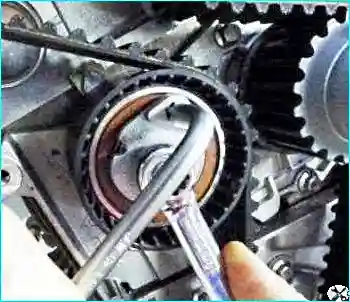
We loosen the tensioner roller and remove the roller.
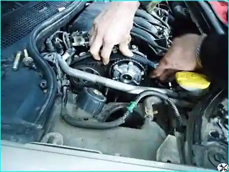
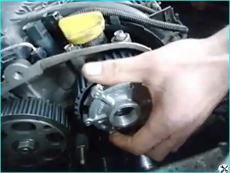
Refitting
Important! We refit the phase regulator in the reverse sequence. When refitting it must be taken into account that the phase regulator must be tightened last.
Before refitting the phase regulator, the bolt and the end of the inlet camshaft must be degreased. The phase regulator mounting point must be clean and degreased.
Tightening torques of the main assemblies when replacing the phase regulator:
- crankshaft pulley securing bolt — 40 N·m and tighten further by 110°;
- camshaft toothed pulley securing nuts — 30 N·m and tighten further by 86° ± 6°;
- guide roller bolts — 50 N·m;
- tensioner roller axle securing nut — 28 N·m.


