


Checking the operation of the vacuum brake booster
Release the existing vacuum with the engine stopped by pressing the brake pedal several times at 5-second intervals.
With the brake pedal fully depressed, start the engine.
Check that, when the vacuum in the engine stabilises, the clearance between the brake pedal and the floor panel decreases.
Leak test
Start the engine and allow it to idle for approximately 1 minute.
Stop it, having applied vacuum to the booster.
Press the brake pedal several times with normal force to release the existing vacuum.
Check that, as the brake pedal is depressed, the clearance between the pedal and the floor panel gradually increases.
Start the engine.
Depress the brake pedal and hold it down, then stop the engine.
Keep the pedal depressed for about 30 seconds or more and check that the pedal travel does not change.
If it does, check:
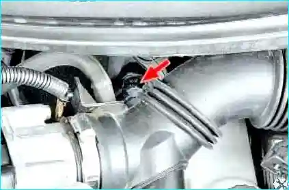
Fig. 1. Check the seal of the hose connector in the vacuum brake booster port
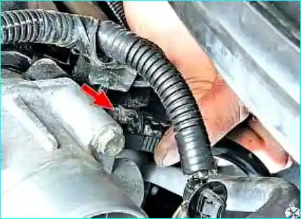
Fig. 2. Check the seal of the hose on the intake manifold connector
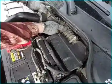
Fig. 3. To check the non-return valve, remove the air intake duct
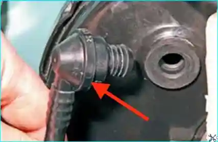
Fig. 4. A non-return valve is fitted in the vacuum hose connector
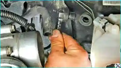
Fig. 5. Disconnect the vacuum hose connector from the brake booster
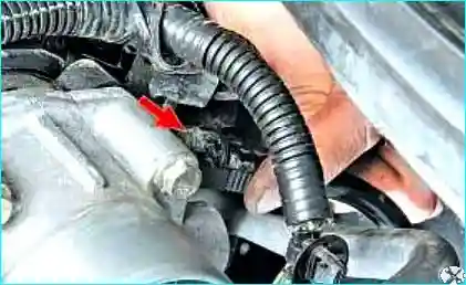
Fig. 6. Release the clip of the vacuum hose connector
For the check, you will need a rubber bulb.
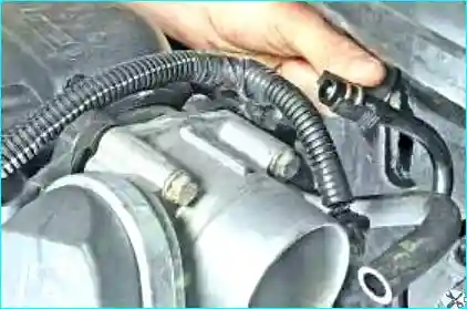
Fig. 7. Remove the hose from the intake manifold connector
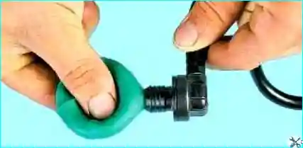
Fig. 8. Insert the rubber bulb firmly into the vacuum hose connector and squeeze the bulb
Air must pass freely through the non-return valve.
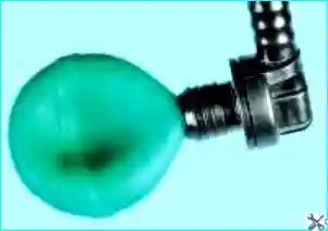
Fig. 9. Release the squeezed bulb. If the bulb expands, the non-return valve is faulty
Replacing the vacuum brake booster
Disconnect the negative battery terminal.
Fig. 10. Loosen the clips and remove the air intake duct
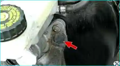
Fig. 11. Prise out the sound insulation retaining clip and pull the sound insulation downwards

Fig. 12. Unscrew the two master cylinder nuts and move the master cylinder aside without disconnecting the brake pipes (in the photo, the pipes are disconnected)
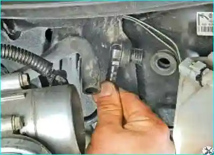
Fig. 13. Disconnect the vacuum hose connector from the vacuum booster
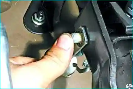
Fig. 14. Remove the retaining pin and press out the pin from the hole in the vacuum booster pushrod fork and the brake pedal
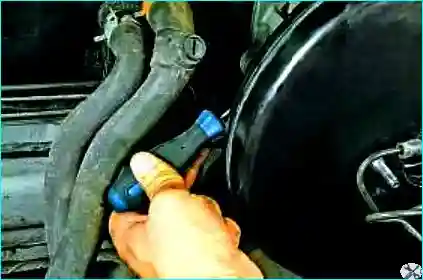
Fig. 15. Remove the bracket retaining clip from the vacuum booster
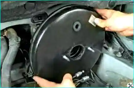
Fig. 16. Turn the vacuum booster a quarter turn in either direction
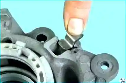
Fig. 17. This is what the vacuum booster retaining clip looks like
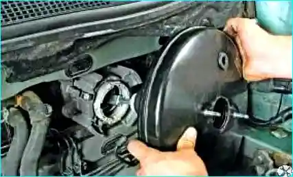
Fig. 18. Withdraw the vacuum booster from the bracket opening
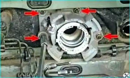
Fig. 19. Unscrew the four bracket mounting nuts to the body
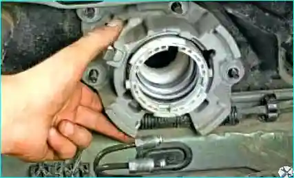
Fig. 20. Remove the bracket
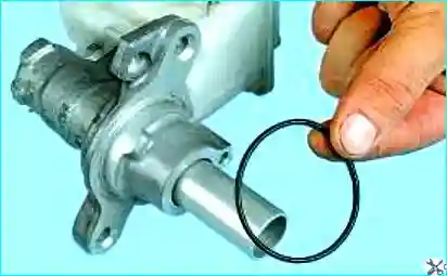
Fig. 21. When replacing the vacuum booster, the master cylinder O-ring must be replaced
Installation
Installation is carried out in the reverse order of removal.
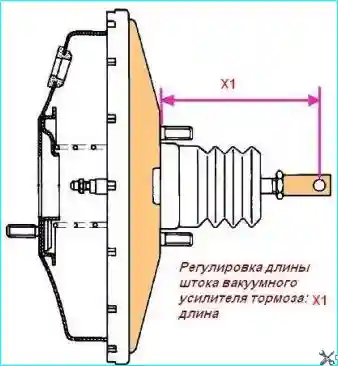
Fig. 22. Adjusting the vacuum brake booster pushrod length: Х1 - length
Before installation, measure the fork pushrod length (Fig. 22):
- for left-hand drive vehicles: Х1 = 163.7 mm;
- for right-hand drive vehicles: Х1 = 133.2 mm.
If the length does not match the specified value, replace the booster.
Check that the connecting pin between the vacuum booster pushrod and the brake pedal is present and locked.
Install the vacuum booster without attaching the pushrod to it.
Tighten the two vacuum booster mounting bolts to 21 N·m.
Install the master cylinder onto the vacuum booster.
Tighten the two master cylinder mounting nuts to 50 N·m.