


To remove the steering column, the driver's airbag, the steering wheel and the steering column cover must be removed.
Therefore, we will examine the entire process step by step.
Removing the steering column
Prepare the vehicle for the procedure.
Disconnect the negative battery terminal.

Fig. 1. Position the steering wheel as shown in the photo
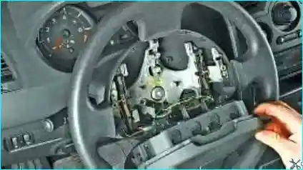
Fig. 2. Remove the driver's airbag module — Removing the airbags on a Renault Megane 2
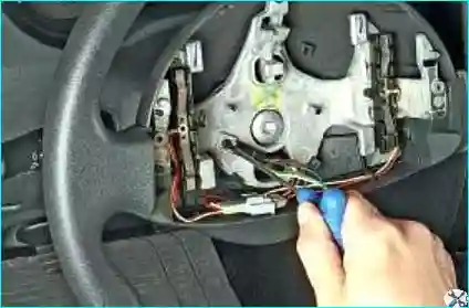
Fig. 3. Unscrew the earth cable retaining screw from the steering wheel
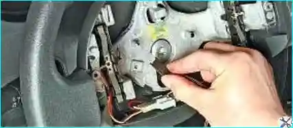
Fig. 4. Remove the earth cable terminal
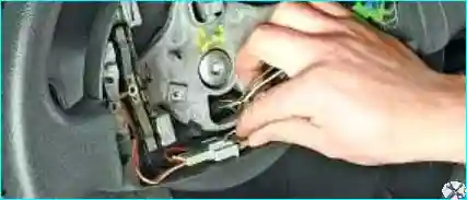
Fig. 5. Release the horn switch wiring connector clip. Disconnect the horn connector
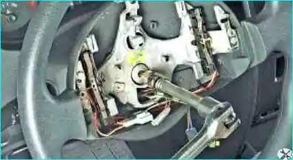
Fig. 6. Unscrew the steering wheel retaining bolt while holding the wheel to prevent it from turning
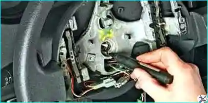
Fig. 7. Mark the position of the steering wheel hub relative to the shaft. Then screw the bolt back in a few turns
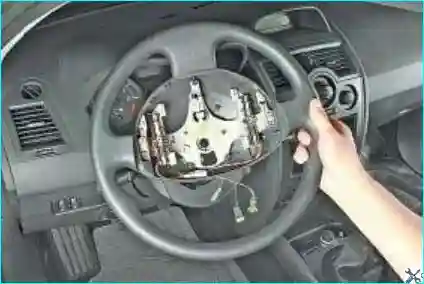
Fig. 8. With sharp blows from both hands on the back of the steering wheel, free it from the shaft splines
Unscrew the steering wheel retaining bolt and remove the steering wheel.
Remove the steering column cover:
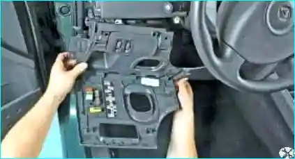
Fig. 9. Remove the left instrument panel trim — Replacing the instrument panel on a Renault Megane II
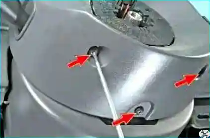
Fig. 10. Unscrew the three screws securing the lower rear and upper parts of the cover
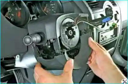
Fig. 11. Remove the lower rear part
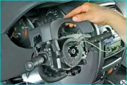
Fig. 12. Remove the upper part of the cover
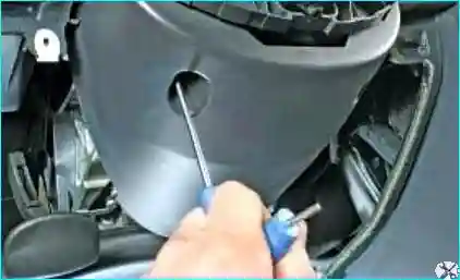
Fig. 13. Unscrew the two screws of the lower front part of the cover
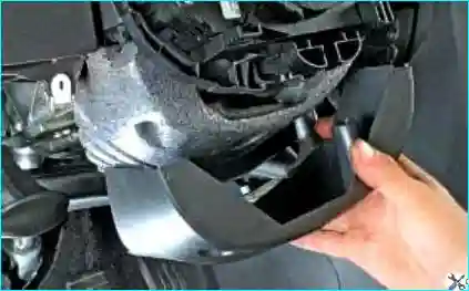
Fig. 14. Remove the steering column cover
Remove the wiring harness holder for the steering column switches, horn switch and driver's airbag module from the energy absorption element.
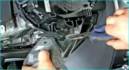
Fig. 15. Remove the energy absorption element from the steering column
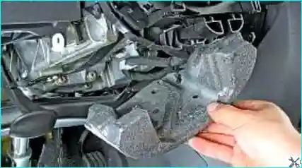
Fig. 16. Begin removing the steering column
To do this, remove the airbag module as described in the article — «Removing the airbags on a Renault Megane 2».
Remove the steering wheel and steering column cover as described above.
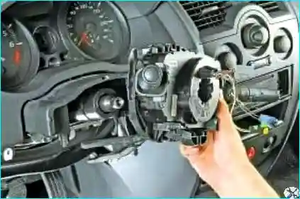
Fig. 17. Move the steering column switches away from the column as far as the wiring allows
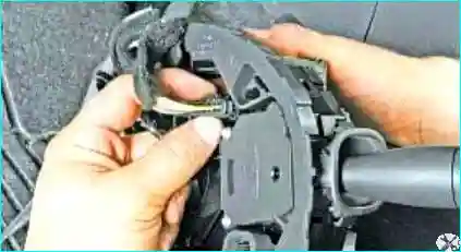
Fig. 18. Release the right switch wiring connector clip
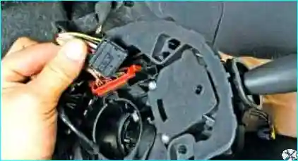
Fig. 19. Disconnect the connector from the steering column switch holder
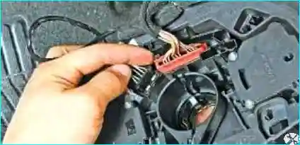
Fig. 20. Release the airbag module wiring connector clip
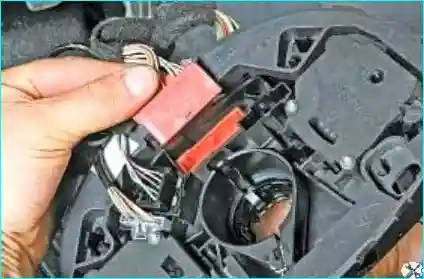
Fig. 21. Disconnect the connector from the steering column switch housing
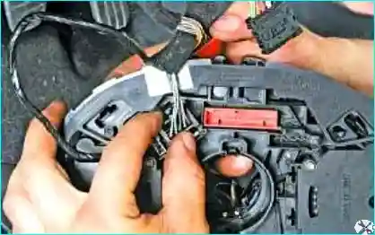
Fig. 22. Release the left switch wiring connector clip
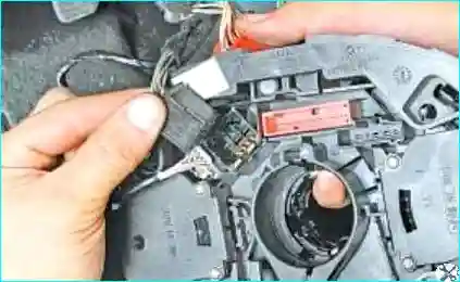
Fig. 23. Disconnect the connector from the steering column switch housing
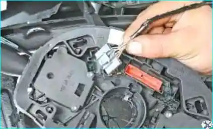
Fig. 24. Remove the audio system control wiring connector from the switch housing
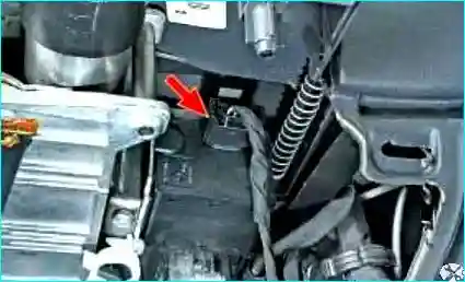
Fig. 25. Disconnect the steering column anti-theft lock mechanism wiring connector
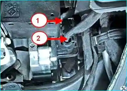
Fig. 26. Disconnect connector 1 of the power steering control unit and connector 2 of the power steering motor
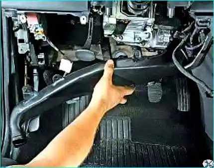
Fig. 27. Remove the heater air duct
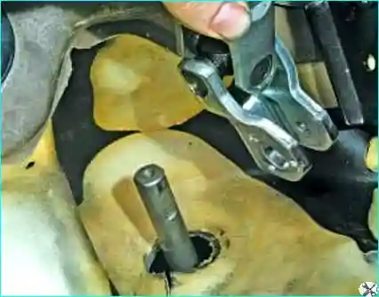
Fig. 28. Remove the lower universal joint of the intermediate shaft from the steering gear pinion shaft
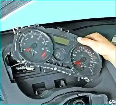
Fig. 29. Remove the instrument cluster — article: Instrument cluster replacement on a Renault Megane II
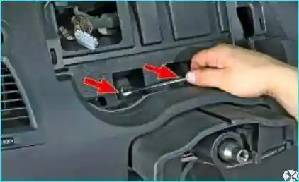
Fig. 30. Unscrew the two nuts securing the steering column to the instrument panel
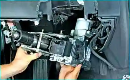
Fig. 31. Remove the steering column from the vehicle
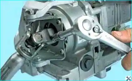
Fig. 32. Unscrew the clamp bolt of the upper universal joint of the intermediate shaft
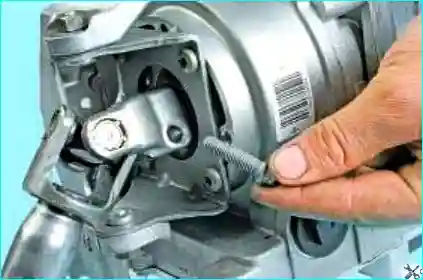
Fig. 33. Remove the clamp bolt from the hole
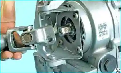
Fig. 34. Disconnect the clamp connection of the upper universal joint from the steering shaft
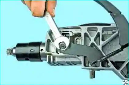
Fig. 35. Unscrew the nut securing the steering column adjustment lever
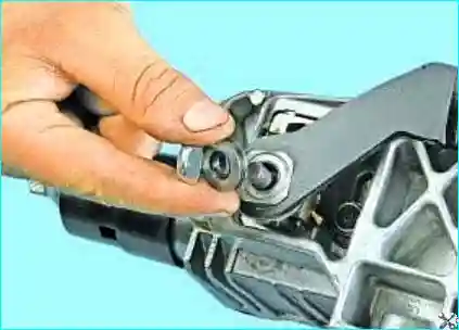
Fig. 36. Remove the nut and thrust washer
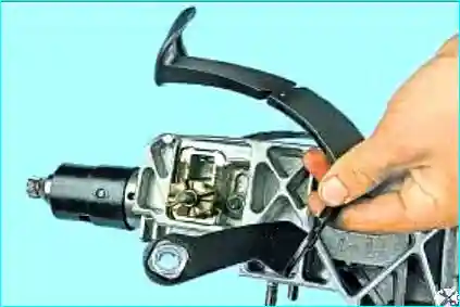
Fig. 37. Remove the steering column adjustment lever
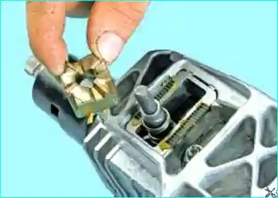
Fig. 38. Remove the cam washer
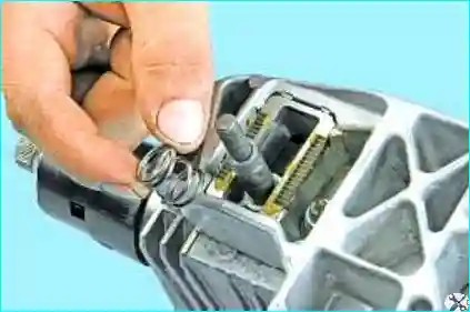
Fig. 39. Remove the spring
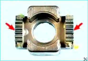
Fig. 40. If the teeth of the cam washer are worn, replace it
After repair, install all components in the reverse order.
Installation
Installation is carried out in the reverse order of removal.
The steering wheel must slide freely onto the splines (the splines have locating sections).
Be careful not to damage the splines on the locating sections. The steering wheel retaining bolt must be replaced after every removal.
The bolt and eccentric nut of the universal joint fork must be replaced after every removal.
The new steering column is fitted with the eccentric nut on the universal joint fork.
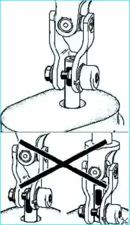
Fig. 41. Installing the bolt and eccentric nut on the universal joint fork
Observe the installation direction of the bolt and eccentric nut (Fig. 41).
Screw in the eccentric nut and bolt.
Secure the clamp connection nut in its socket (hole in the universal joint fork).
Tighten to the specified torque:
- the steering column retaining nuts (21 N·m);
- the universal joint fork clamp connection bolt (21 N·m).
Connect the cables to the battery terminals, starting with the positive terminal.
Perform a full check using a diagnostic tool.
Clear the fault codes that appeared during the work from the memory using the diagnostic tool.


