
The electronic engine control system is a complex system designed to prepare the air-fuel mixture in a certain proportion and quantity necessary for various engine operating modes
The system meets modern emission and fumes regulations while maintaining high driving performance and low fuel consumption.
The control device in the system is the electronic control unit (ECU, controller).
Based on the information received from the sensors, the ECU calculates the parameters for fuel injection control and ignition timing control.
In addition, in accordance with the embedded algorithm, the ECU controls the electric motor of the fan of the engine cooling system and the electromagnetic clutch for turning on the air conditioning compressor, performs the function of self-diagnostics of the system elements and notifies the driver of any malfunctions.
If individual sensors and actuators fail, the ECU turns on emergency modes that ensure engine performance.
The amount of fuel supplied by the injectors is determined by the duration of the electrical signal from the ECU.
The electronic unit monitors data on the state of the engine, calculates the need for fuel and determines the required duration of fuel supply by the injectors (signal duration).
To increase the amount of fuel supplied, the duration of the signal increases, and to decrease the amount of fuel, it decreases.
The engine management system, along with the electronic control unit, includes sensors, actuators, connectors and fuses.
Electronic control unit (ECU)
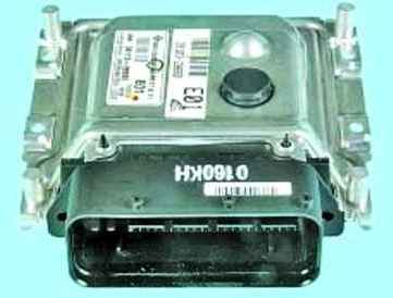
The electronic control unit is connected by electrical wires to all sensors of the system.
Receiving information from them, the block performs calculations in accordance with the parameters and control algorithm stored in the memory of the programmable read-only memory (PROM), and controls the system's executive devices.
The program variant recorded in the PROM memory is indicated by the number assigned to this ECU modification.
The control unit detects a fault, identifies and remembers its code, even if the fault is unstable and disappears (for example, due to poor contact).
The engine control system malfunction indicator in the instrument cluster goes out 10 seconds after the failed unit is restored.
After repair, the fault code stored in the memory of the control unit must be erased.
To do this, turn off the power to the unit for 10 seconds (remove the fuse for the power supply circuit of the electronic control unit or disconnect the wire from the negative terminal of the battery).
The unit supplies DC voltage of 5 and 12 V to various sensors and switches of the control system.
Because the electrical resistance of the power circuits is high, the test lamp connected to the system outputs does not light up.
To determine the supply voltage at the computer terminals, use a voltmeter with an internal resistance of at least 10 MΩ.
The ECU is not repairable, so if it fails, it must be replaced.
Crankshaft position sensor
The crankshaft position sensor is designed to synchronize the operation of the electronic engine control unit with the angular position of the crankshaft.
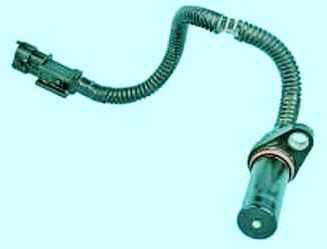
The action of the sensor is based on the Hall effect.
The sensor is mounted at the rear of the engine opposite the drive ring on the flywheel. The driving ring is a gear wheel with cavities.
Two teeth are sheared to create a synchronization pulse ("reference" pulse), which is necessary to coordinate the operation of the control unit with the TDC of pistons in the 1st and 4th cylinders.
As the crankshaft rotates, the teeth change the magnetic field of the sensor, inducing AC voltage pulses.
The control unit determines the crankshaft speed using the sensor signals and sends pulses to the injectors.
If the sensor fails, the engine cannot be started.
Camshaft position sensor
An inductive type camshaft position sensor is installed at the front of the cylinder head.
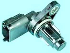
As the intake camshaft rotates, the protrusions on its front journal change the magnetic field of the sensor, inducing AC voltage pulses.
Sensor signals are used by the ECU to organize phased fuel injection in accordance with the order of operation of the cylinders, as well as to control the change in valve timing depending on the engine operating mode.
If a malfunction occurs in the camshaft position sensor circuit, the electronic unit memorizes its code and turns on the engine control system malfunction indicator.
Coolant temperature sensor
The coolant temperature sensor is installed in the engine cooling system.
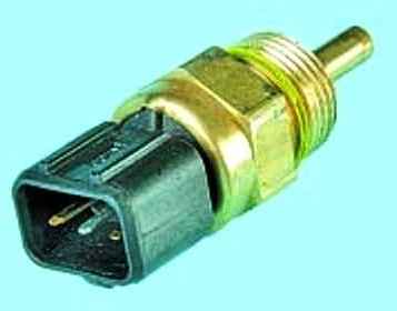
The sensing element of the sensor is a thermistor, the electrical resistance of which changes inversely with temperature.
At a low coolant temperature (-20 °C), the resistance of the thermistor is about 15 kOhm, when the temperature rises to +80 °C, the resistance decreases to 320 Ohm.
The electronic unit supplies the temperature sensor circuit with a constant "reference" voltage.
The voltage of the sensor signal reaches its maximum value on a cold engine and decreases as it warms up.
The electronic unit determines the engine temperature from the voltage value and takes it into account when calculating the injection and ignition control parameters.
If the sensor fails or there are violations in its connection circuit, the ECU sets the fault code and remembers it.
An additional thermistor is also installed in the sensor housing to control the coolant temperature gauge in the instrument cluster.
Throttle position sensor
The throttle position sensor is mounted on the throttle body and is connected to the throttle valve axis.
The sensor is a potentiometer, one end of which is supplied with a "plus" supply voltage (5 V), and the other end is connected to "ground"
The third output of the potentiometer (from the slider) is the output signal to the electronic control unit.
When the throttle valve is turned (from actuation on the drive pedal), the voltage at the output of the sensor changes. It is less than 0.5 V when the throttle is closed.
When the damper opens, the voltage at the sensor output rises; when the damper is fully open, it should be more than 4 V.
By monitoring the output voltage of the sensor, the ECU adjusts the fuel supply depending on the throttle opening angle (i.e. at the request of the driver).
The throttle position sensor does not require adjustment, as the control unit perceives idling (i.e. full throttle closing) as a zero mark.
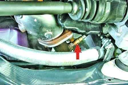
Control oxygen sensor
The control oxygen concentration sensor is used in the feedback injection system and is installed in the downpipe.
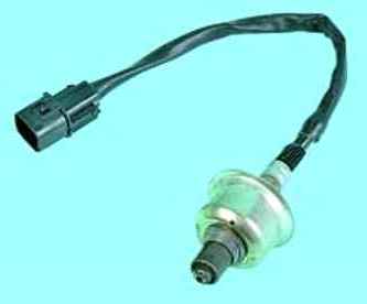
In order to correct the calculations of the duration of the injection pulses, information on the presence of oxygen in the exhaust gases is used, this information is provided by the control oxygen concentration sensor.
The oxygen contained in the exhaust gases reacts with the sensor, creating a potential difference at the sensor output.
It varies from approximately 0.1V (high oxygen - lean) to 1V (low oxygen - rich).
By monitoring the output voltage of the oxygen concentration sensor, the ECU determines which command to adjust the composition of the working mixture to apply to the injectors.
If the mixture is lean (low potential difference at the sensor output), then the controller gives a command to enrich the mixture; if the mixture is rich (high potential difference) - to deplete the mixture.
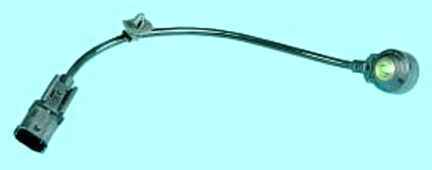
Diagnostic oxygen sensor
The diagnostic oxygen sensor works on the same principle as the control sensor.
The signal generated by the diagnostic oxygen sensor indicates the presence of oxygen in the exhaust gases after the converter.
If the converter is working properly, the readings of the diagnostic sensor will differ significantly from the readings of the control sensor.
Information from each sensor enters the control unit in the form of low (from 0.1 V) and high (up to 0.9 V) level signals.
At a low level signal, the control unit receives information about a high oxygen content. A high level signal indicates a low oxygen content in the exhaust gases.
Constantly monitoring the voltage of the sensor signal, the control unit adjusts the amount of fuel injected by the injectors.
When the sensor signal level at the collector inlet is low (lean air-fuel mixture), the amount of fuel supplied increases, and when the signal level is high (rich mixture), it decreases.
Knock sensor
The knock sensor is attached to the top of the cylinder block in the area between the 2nd and 3rd cylinders and detects abnormal vibrations (knock) in the engine.
The sensing element of the knock sensor is a piezoelectric plate.
During detonation, voltage pulses are generated at the output of the sensor, which increase with increasing intensity of detonation impacts.
The electronic unit, based on the sensor signal, regulates the ignition timing to eliminate detonation fuel flashes.
During operation, the ECU also uses the vehicle speed data received from the ABS control unit.
On versions of the car not equipped with ABS, the speedometer sensor installed in the gearbox or a separate sensor for the speed of the right front wheel is used for this purpose.
Manifold absolute pressure sensor
The absolute pressure sensor in the intake pipe converts the degree of vacuum in this pipe into a change in electrical voltage, according to the value of which the ECU sets the parameters of the engine.
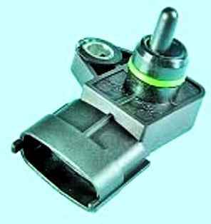
The sensor is mounted on the intake pipe.
The output voltage of the sensor varies according to the pressure in the intake pipe - from 4.0 V (at wide open throttle) to 0.79 V (at closed throttle).
When the engine is not running, the control unit determines the atmospheric pressure from the sensor voltage and adapts the injection control parameters to the specific altitude.
Atmospheric pressure values stored in the memory are periodically updated when the vehicle is in steady motion and during full throttle opening.
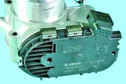
Variable valve timing solenoid valve
The solenoid valve for the variable valve timing system is installed in the engine cylinder head.
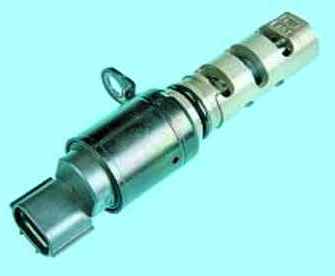
The valve regulates the oil pressure supplied to the timing actuator mounted on the forward end of the intake camshaft.
The system performs optimal tuning of the valve timing, changing them over the entire range of engine frequency and load, which increases power and torque at any speed.
When the engine is stopped, oil pressure causes the control valve spool to move to the position corresponding to the latest valve timing.
The control valve is triggered by a signal from the engine control unit and supplies oil either to the lag chamber or to the advance chamber with a continuous change in the valve timing, respectively, either in the direction of their advance or in the direction of delay.
The diagnostic connector is used to display fault codes detected during the operation of the engine management system from the computer memory.
Diagnostic connector
The diagnostic connector is located in the passenger compartment on the left side under the decorative cover of the mounting block.
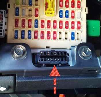
You can connect a scanning device to the diagnostic socket that reads information from the serial data bus.

")
")
")
")
")
")
")
")