Four-cylinder four-stroke engines DOHC CWT 1.4 and 1.6 liters have been installed on Hyundai Solaris cars since 2011.
Engines differ only in crankshaft radius and cylinder block height.
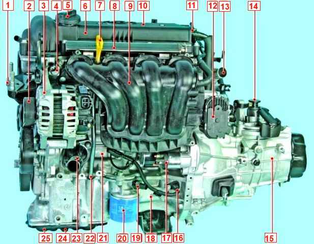
The camshafts are driven by a chain.
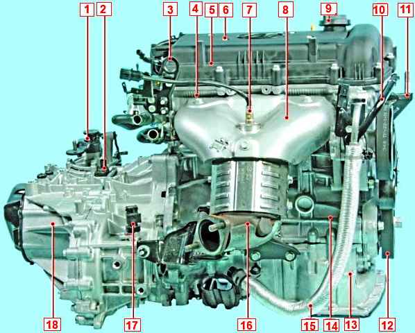
The position of the camshaft phase is corrected by the electronic system (CWT)
This system allows you to set the optimal valve timing for each moment of engine operation.
The result is more power, less toxicity and better fuel economy.
The phase control mechanism is a hydraulic mechanism that is connected to the engine oil line.
Oil from the lubrication system enters the gas distribution mechanism through channels.
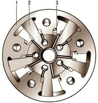
Rotor 2 (Fig. 3) turns the camshaft at the command of the electronic engine control unit.
To determine the position of the camshaft, a camshaft position sensor is installed at the rear of the camshaft.
On the camshaft journal there is a sensor position setting ring.
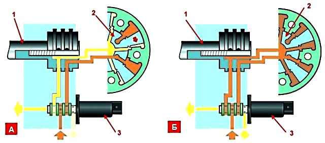
A solenoid valve is installed on the cylinder head, which hydraulically controls the mechanism.
The solenoid valve, in turn, is controlled by the electronic engine control unit.
The use of the phase control mechanism ensures a smooth change in the angle of installation of the intake camshaft in the position of early and late opening of the gas distribution valves.
The control unit determines the position of the camshaft from the signals of the camshaft position sensor and the crankshaft sensor and issues a command to change the position of the intake camshaft.
In accordance with this command, the spool of the solenoid valve is moved, for example, in the direction of more advanced opening of the intake valves.
In this case, the oil supplied under pressure enters through the channel in the timing case into the case of the phase regulator mechanism and causes the camshaft to rotate in the required direction.
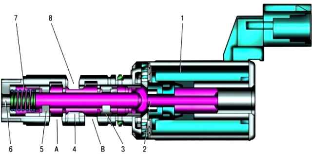
Solenoid valve of the variable valve timing system: 1 - electromagnet; 2 - valve spool; 3 - an annular groove connected by a channel in the cylinder head cover with the second working chamber of the mechanism for changing the valve timing; 4 - annular groove for oil drainage; 5 - an annular groove connected by a channel in the cylinder head cover with the first working chamber of the mechanism for changing the valve timing; 6 - hole for supplying oil from the main line; 7 - valve spring; 8 - hole for draining oil; A - a cavity connected by a channel in the cylinder head cover with the first working chamber of the fluid coupling of the variable valve timing mechanism; B - a cavity connected by a channel in the cylinder head cover with the second working chamber of the variable valve timing mechanism
When the spool is moved in the direction corresponding to the earlier opening of the valves, the channel for their later opening is automatically connected to the drain channel.
If the camshaft has turned to the required angle, the solenoid valve spool (Fig. 5) is set to a position at the command of the control unit, in which the oil is maintained under pressure on both sides of each of the clutch rotor blades.
If it is required to turn the camshaft towards a later opening of the valves, the control process is carried out with oil supply in the opposite direction.
The components of the CVVT system (solenoid valve and dynamic camshaft position change mechanism) are precision-manufactured assemblies.
In this regard, when performing maintenance or repair of the variable valve timing system, only the replacement of the complete system elements is allowed.
The cylinder head of the engines is made of aluminum alloy according to the transverse cylinder scavenging pattern (inlet and outlet channels are located on opposite sides of the head).
Saddles and valve guides are pressed into the head.
The engine block is a single casting of a special aluminum alloy that forms the cylinders, the cooling jacket, the upper part of the crankcase and the five crankshaft bearings.
Five main bearing beds are made in the lower part of the block.
The cylinder block has special lugs, flanges and holes for attaching parts, components and assemblies, as well as channels of the main oil line.
The crankshaft rotates in main bearings with thin-walled steel liners with an anti-friction layer.
The crankshaft of the engine is fixed from axial movements by two half rings installed in the grooves of the bed of the middle main bearing.
The flywheel is cast iron, mounted on the rear end of the crankshaft through a mounting sleeve and secured with six bolts. A toothed rim is pressed onto the flywheel for starting the engine with a starter.
On vehicles with an automatic transmission, a torque converter drive disc is installed instead of a flywheel.
The pistons are made of aluminum alloy.
On the cylindrical surface of the piston head, annular grooves are made for the oil scraper and two compression rings.
Pistons are additionally cooled by oil supplied through a hole in the upper head of the connecting rod and sprayed onto the piston crown.
The piston pins are installed in the piston bosses with a gap and are pressed with an interference fit into the upper heads of the connecting rods, which are connected with their lower heads to the connecting rod journals of the crankshaft through thin-walled liners, the design of which is similar to the main ones.
Steel connecting rods, forged, with an I-section shank.
Combined lubrication system
The closed-type crankcase ventilation system does not communicate directly with the atmosphere, therefore, simultaneously with the exhaust of gases, a vacuum is formed in the crankcase under all engine operating modes, which increases the reliability of various engine seals and reduces the emission of toxic substances into the atmosphere.
The system consists of two branches, large and small.
When the engine is idling and in low load modes, when the vacuum in the intake pipe is high, crankcase gases are sucked in by the intake pipe through the crankcase ventilation valve installed on the cylinder head cover.
The valve opens depending on the vacuum in the intake pipe and thus regulates the flow of crankcase gases.
In full load modes, when the throttle valve is open at a large angle, the vacuum in the intake pipe decreases, and in the air supply hose it increases, crankcase gases through the large branch hose connected to the fitting on the head cover, mainly step into the air supply sleeve, and then through the throttle assembly - into the intake pipe and into the engine cylinders.
The engine cooling system is sealed, with an expansion tank, and consists of a cooling jacket made in casting and surrounding the cylinders in the block, combustion chambers and gas channels in the cylinder head.
The forced circulation of the coolant is provided by a centrifugal water pump driven by a crankshaft poly V-belt, which simultaneously drives the generator.
To maintain the normal operating temperature of the coolant, a thermostat is installed in the cooling system, which blocks a large circle of the system when the engine is cold and the coolant temperature is low.
The engine power supply system consists of an electric fuel pump installed in the fuel tank, a throttle assembly, a fine fuel filter located in the fuel pump module, a fuel pressure regulator, injectors and fuel lines, and also includes an air filter.
The engine ignition system is microprocessor-based and consists of coils and spark plugs.
The electronic unit (controller) of the engine management system controls the ignition coils.
The ignition system does not require maintenance and adjustment during operation.
The power unit (engine with gearbox, clutch and final drive) is mounted on three supports with elastic rubber elements: two upper side supports (right and left) that take the bulk of the power unit, and a rear one that compensates for the torque from the transmission and load that occur when starting the car, accelerating and braking.
Possible engine malfunctions and solutions
Cause of malfunction Remedy
Engine won't start
No pressure in the fuel rail:
Clogged fuel lines - Flush and bleed fuel lines
Fuel pump defective - Check and replace pump
Clogged fuel filter - Replace fuel filter
Faulty fuel pressure regulator - Check fuel pressure regulator
Faulty ignition system - Check engine ignition system
Engine runs erratically or stalls at idle:
Insufficient pressure in the fuel rail - See fault - engine will not start
Faulty idle speed control - Replace idle speed control
Air leakage through the crankcase ventilation hose and the hose connecting the intake pipe to the vacuum brake booster - Tighten the fastening clamps, replace damaged hoses
Ignition system malfunction - Check the ignition system elements, replace faulty sensors or elements
The engine does not develop full power and there is no acceleration:
Faulty throttle position sensor - Replace throttle body
Insufficient pressure in the fuel rail - See above fault - engine does not start
Air filter dirty - Replace filter element
Ignition system faulty - Check the ignition system elements, replace faulty sensors or elements
Insufficient compression, below 1 MPa (10kgf/cm2) - Check and repair the piston-cylinder group
Insufficient oil pressure in a warm engine:
Oil does not match the brand - Change the oil with the recommended one
Oil thinning or foaming due to fuel or coolant getting into the oil - Repair and change the oil
Worn oil pump parts - Replace oil pump
Clogged oil filter - Change oil filter
Worn crankshaft main and connecting rod bearings - Grind the crankshaft journals and replace the bearings
Cracks, pores in the walls of the oil channels of the cylinder block or clogging of the oil lines - Replace the block or repair
Knock of crankshaft main bearings:
Usually a dull, metallic sound.
Detected when the throttle is suddenly opened at idle.
Its frequency increases with increasing crankshaft speed.
Excessive axial clearance of the crankshaft causes a sharper knock with uneven intervals, especially noticeable with a smooth increase and decrease in the crankshaft speed
Increased clearance between journals and main bearing shells - Grind journals and replace bearing shells
Loose flywheel mounting bolts - Replace bolts and tighten to recommended torque
Increased clearance between the thrust flanges of the middle main bearing shells and the crankshaft - Replace the half rings with new ones, check the clearance
Rattle of connecting rod bearings
Usually, the knock of the connecting rod bearings is sharper than the knock of the main bearings.
It is heard at idle speed of the engine with a sharp opening of the throttle.
Stu place it is easy to determine by turning off the spark plugs in turn
Insufficient oil pressure - See fault - insufficient oil pressure
Large gap between bearings and crankpins - Grind crankshaft and replace bearings
The sound of pistons
The knock is usually unvoiced, muffled, caused by the beating of the piston in the cylinder.
It is best heard at low engine speeds and under load
Increased clearance between pistons and cylinders - Replace pistons, bore and refinish cylinders
Excessive clearance between piston rings and piston grooves - Replace rings or pistons with rings
Increased gas distribution noise
Low oil pressure in the lubrication system - See fault - insufficient oil pressure
Camshaft Lobe Wear - Replace Camshaft
Short-term knocks immediately after starting the engine
Oil mismatch (low viscosity oil) - Change oil
Increased crankshaft axial clearance - Replace thrust washers
Increased front main bearing clearance - Replace front main bearing shells
Knocking in a warm engine at idle
Loose or worn accessory drive belt - Adjust or replace belt
Noise of timing parts - See malfunction - noise of the gas distribution mechanism
Using the wrong brand of oil - Change the oil to the correct one
Increased clearances between piston pins and piston boss bores - Replace pistons and pins
Increased connecting rod bearing clearances - Replace bearings and grind crankshaft journals
Axes of the upper and lower connecting rod are not parallel - Replace the connecting rod
Strong knocks in a warm engine when the crankshaft speed is increased
Accessory drive belt too tight or cracked or broken - Adjust belt tension or replace belt
Loose flywheel - Torque tighten flywheel bolts
Worn bearings and crankshaft journals - Grind the crankshaft or replace the crankshaft and bearings
Engine knocking when under load
Using Low Octane Gasoline - Change Gasoline
Increased oil consumption
Breakage or wear of piston - Replace piston or rings
Oil leaking through engine seals - Tighten fasteners or replace gaskets and seals
Crankcase ventilation system clogged - Flush and purge engine crankcase ventilation system
Worn valve stems or guide bushings and valve stem seals - Replace valve stem seals and repair cylinder head
Engine overheating
Insufficient amount of fluid in the cooling system - Add coolant
Thermostat is defective - Replace the thermostat
The cooling fan is defective - Replace the electric fan or the sensor for turning it on and the relay
The radiator is dirty - Clean the radiator or replace it
Faulty radiator cap valve - Replace radiator filler cap
Using Low Octane Gasoline - Change Gasoline
Quick drop in the liquid level in the expansion tank
Radiator damaged - Replace radiator
Hose or gaskets damaged - Replace hoses or gaskets
Liquid leakage through microcracks in the block or in the cylinder head - Check the tightness of the block and cylinder head
With a certain skill and care, many malfunctions of the engine and its systems can be quite accurately determined by the color of the smoke coming out of the exhaust pipe.
Blue smoke indicates that oil has entered the combustion chambers, and constant smoke is a sign of severe wear of the parts of the cylinder-piston group.
The appearance of smoke during regassing, after prolonged cranking by the starter, after long idling or immediately after engine braking, as a rule, indicates wear on the valve stem seals.
Black smoke is caused by too rich a mixture due to a malfunction of the engine control system or injectors.
Blue or thick white smoke with moisture (especially after the engine has overheated) means that coolant has entered the combustion chamber through a damaged cylinder head gasket.
If this gasket is severely damaged, the liquid sometimes enters the oil sump, the oil level rises sharply, and the oil itself turns into a cloudy whitish emulsion. White smoke (steam) when the engine is cold in wet or cold weather is normal.
It is quite common to see a car parked in the middle of a city traffic jam with its hood open, emitting puffs of steam.
Overheating
It is better, of course, not to allow this, often looking at temperature indicator. But no one is immune from the fact that the thermostat, electric fans may suddenly fail, or coolant may simply leak.
If you miss the moment of overheating, do not panic and do not aggravate the situation.
Overheating is not as bad as its possible consequences. Never turn off the engine immediately - it will get a heat stroke and, possibly, having cooled down, will refuse to start at all.
Having stopped, let it idle, then the fluid will continue to circulate in the system.
Turn on the heater to maximum power and open the hood.
If possible, pour cold water over the radiator. Stop the engine only when the temperature drops.
But never immediately open the radiator cap: on an overheated engine, a geyser from under the open cap is provided.
Take your time, let things cool down, and you'll save the machine's health and your own health.
Almost all instructions for the car contain a recommendation to depress the clutch when starting the engine.
This recommendation is justified only in case of starting in severe frost, so as not to waste battery energy on turning the shafts and gears of the gearbox in thickened oil.
In other cases, this measure is aimed only at ensuring that the car does not start if the gear is switched on due to forgetfulness.
This technique is harmful to the engine, since when the clutch is depressed, a significant force is transmitted through it to the thrust bearing of the crankshaft, and during start-up (especially cold), lubrication is not supplied to it for a long time.
The bearing wears out quickly, the crankshaft gets axial play, and starting off begins to be accompanied by strong vibration.
In order not to spoil the engine, make it a habit to check the position of the gear lever before starting and start the engine with the handbrake applied, without depressing the clutch unless absolutely necessary.


