


The vehicle's instrument panel, of dismantlable design, consists of a decorative panel and a frame.
The decorative panel is made of plastic and is attached to the frame with screws.
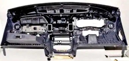
The frame is of steel construction and forms part of the body's load-bearing structure.
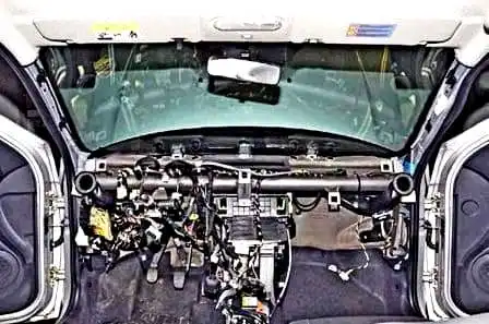
The steering column, the heater and air conditioning unit and the electrical equipment elements are attached to the frame.
We prepare the vehicle to carry out the task. We disconnect the negative terminal of the battery.
We remove the steering wheel (see — Removal and installation of the vehicle steering wheel).
We remove the steering column switches (Design and replacement of the steering column switches).
We remove the instrument cluster (described in the article — Removal of the instrument cluster).
We remove the floor tunnel trim (described in the article — Removal of the floor tunnel trim of the vehicle).
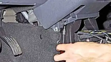
Using a Torx T20 key, we undo the two screws of the lower mounting of the instrument panel console to the body.
We remove the instrument panel console trim (Removal of the vehicle electronic units).
We remove the audio system.
We undo the two screws securing the heating and air conditioning control unit and push the unit inside the instrument panel.
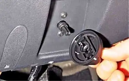
Pulling towards ourselves, we remove the headlight levelling control knob.
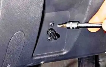
Using a Torx T20 key, we undo the two screws securing the headlight levelling control and push the control inside the instrument panel.
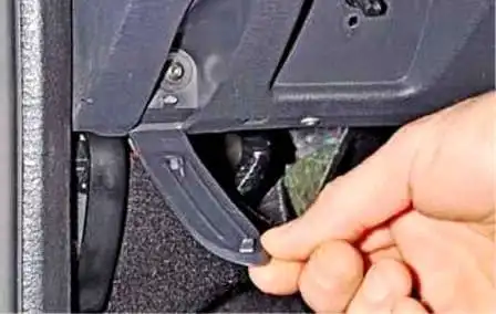
Prising with a screwdriver, we flip open the screw cover of the lower side mounting of the instrument panel.
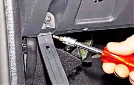
We undo the screw of the side mounting of the instrument panel.
We also undo the screw on the other side of the instrument panel.
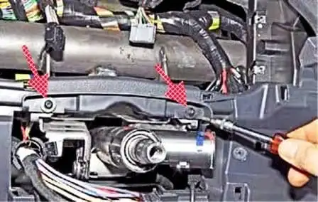
Using a Torx T20 key, we undo the two screws securing the instrument panel above the steering column.
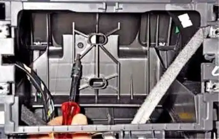
In the audio system recess, using a Torx T20 key, we undo the screw of the central mounting of the instrument panel.
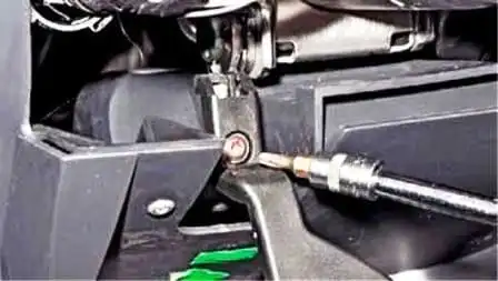
Using a Torx T20 key, we undo the screw securing the steering column lock lever handle.
We open the glovebox and remove the cover from the diagnostic socket.
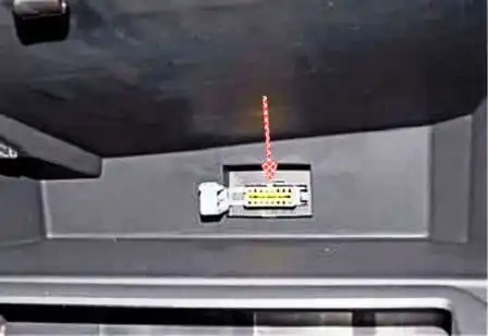
We press the clip (arrow in the figure) and push the socket inside the instrument panel.
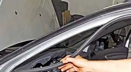
We remove the driver's door seal in the front pillar and instrument panel area.
Also on the passenger side.
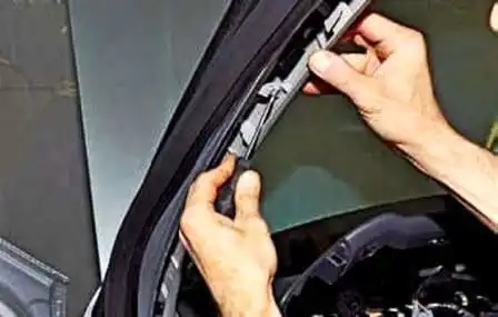
We prise off the left front pillar trim.
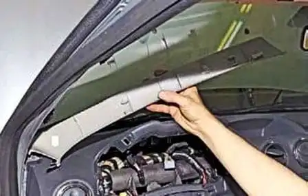
We take the lower clips out of the openings in the instrument panel and remove the left front pillar trim.
We also remove the right front pillar trim.
Using a Torx T20 key, we undo the screw of the upper side mounting of the instrument panel.
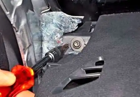
We also undo the screw on the other side of the instrument panel.
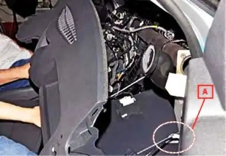
We move the instrument panel away from the crossmember.
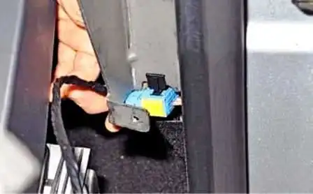
We take the wiring harness connectors out of the opening in the instrument panel crossmember in area «A» (fig. 15).
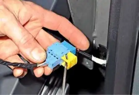
Using a screwdriver, we shift the connector clip.
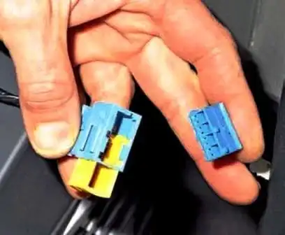
We separate the connectors.
We take the instrument panel out of the vehicle interior.
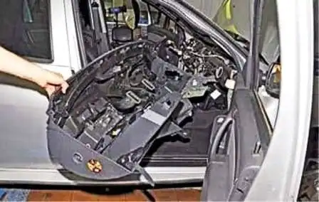
We install the instrument panel in the reverse order.


