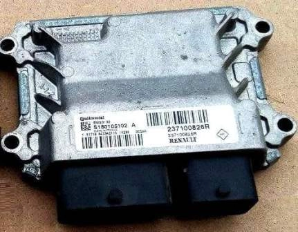
We remove the sensors and the electronic engine control unit for replacement, as well as for repairs.
Replacing the electronic engine control unit
Disconnect the negative battery terminal, then disconnect the positive battery terminal.
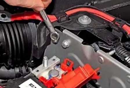
Using a 10 key, unscrew the bolt securing the positive wire bracket to the battery pad bracket
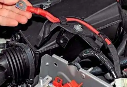
Remove the bracket with wires away from the platform
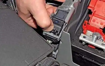
Press the lock of the bracket of the engine control unit wire block
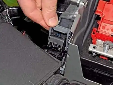
Rotating the shoe bracket
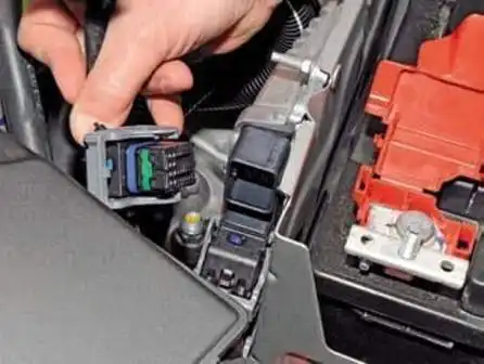
Disconnect the wiring harness block from the top connector of the unit
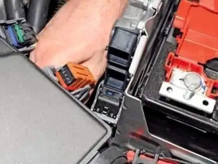
Disconnect the middle block of wires from the block
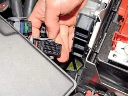
Disconnect the block from the lower connector of the control unit
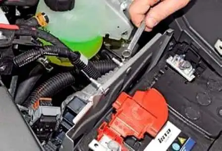
Using a 10 wrench, unscrew the two nuts of the stud bolts of the upper fastening of the control unit to the battery platform bracket
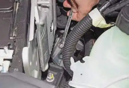
Unscrew the nut of the stud of the lower fastening of the block
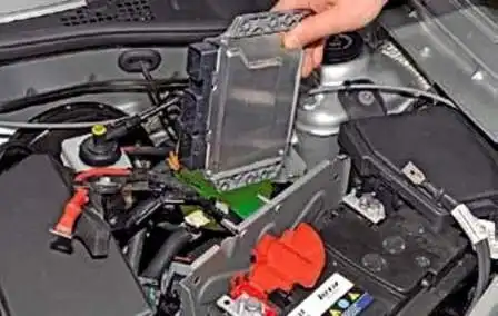
Remove the control unit from the studs of the battery platform bracket and remove it from the engine compartment
Install the block in reverse order.
Removing and installing the crankshaft sensor
We remove the crankshaft sensor for cleaning, replacement, when removing the gearbox.
Depending on the type of engine and gearbox, the sensors differ in design and location.
If a car with a 2.0 liter engine. F4R
We install the car on a viewing ditch or a lift.
Removing the protection of the power plant (article - Removing the engine protection , fender liner and mudguards Renault Duster)
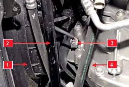
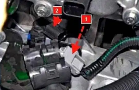
Sensor location is shown in Figure 1
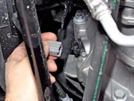
Disconnect the block from the sensor connector
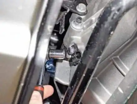
With a head of 10, unscrew the sensor mounting bolt
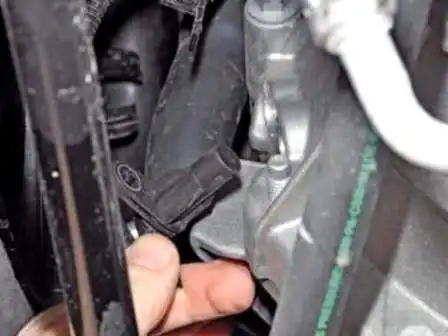
Remove the sensor from the hole in the gearbox housing
Install the crankshaft position sensor in reverse order.
If the car has a 1.6L K4M engine
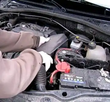
In the engine compartment, remove the air intake and air path resonator
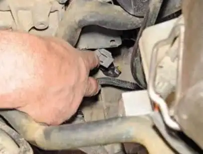
Push on the lock of the engine management system wiring harness
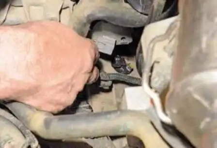
Disconnect the block from the sensor connector
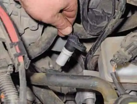
With a head of 10, unscrew the sensor mounting bolt and remove the sensor
Install the sensor in reverse order.
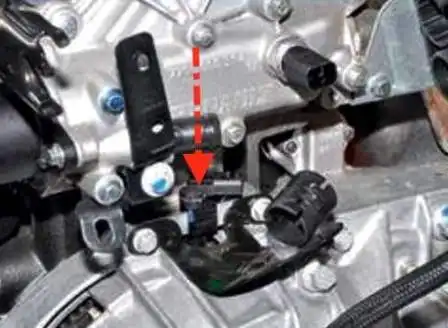
On this engine, the sensor may be of a different design and is installed on the clutch housing, figure 9
Disconnect the block from the sensor connector
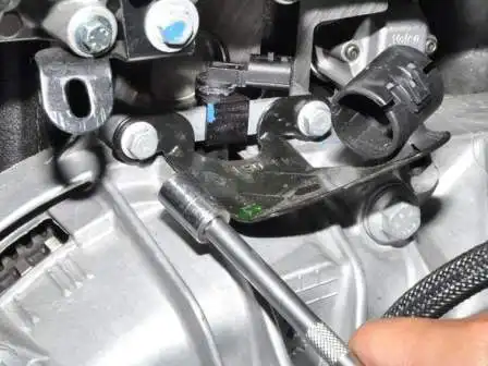
Unscrew the sensor mount with a 10 head
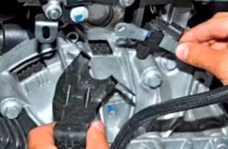
Remove the sensor from the clutch housing
Install the crankshaft position sensor in reverse order.
After replacing the crankshaft sensor, it must be calibrated using a test, which includes:
- - deceleration of the car with a fuel supply cut in II, III, IV or V gear at a speed of 3500-3000 min-1 for at least 2 seconds;
- - re-deceleration with fuel cutoff in II, III, IV or V gear at an engine speed of 2400-2000 min -1 for at least 3 seconds;
- - check for fault codes and, if necessary, troubleshoot;
- - erase codes.
Removing the camshaft position sensor, 2.0l F4R engine
Remove the sensor for replacing or repairing the cylinder head
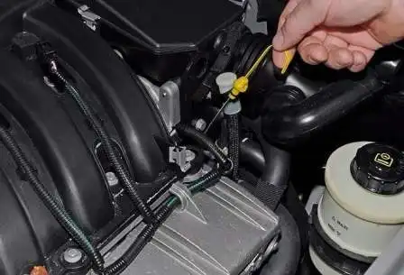
Remove the dipstick

Remove the air intake with a resonator
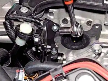
With a head of 8, unscrew the two bolts of the hose attachment bracket (eye)
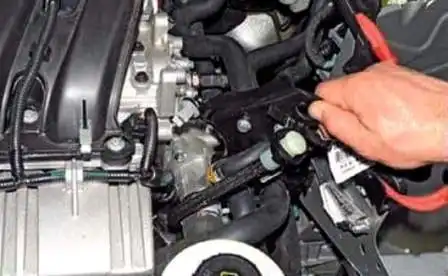
Remove the bracket with hoses from the cylinder head
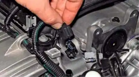
Disconnect the wiring harness from the camshaft position sensor connector
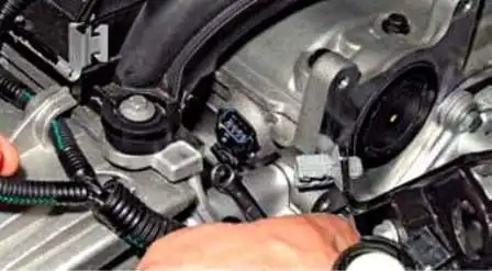
Using an 8 key, unscrew the sensor mounting bolt
Remove the sensor from the bore of the cylinder head
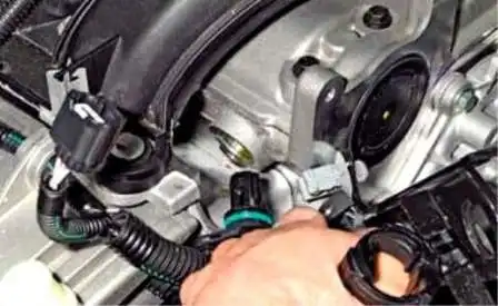
Install the sensor in reverse order, replacing the O-ring.
Removing the absolute air pressure sensor
The sensor is mounted on the intake pipe.
The sensor detects the change in pressure (vacuum) in the intake pipe depending on the change in load and engine speed and converts them into an output signal voltage.
Depending on the sensor signal, the ECU calculates the amount of air entering the engine.
No tool is required to replace the sensor.
Disconnect the negative battery terminal
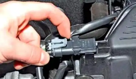
We press the retainer of the engine control harness block
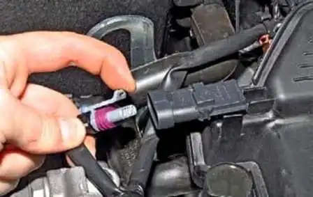
Disconnect the wiring harness from the sensor connector
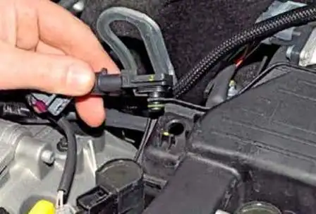
Remove the sensor from the hole in the receiver.
We replace damaged sealing rings in case of defects. Install the sensor in reverse order.
Replacing the air temperature sensor in the intake pipe
A sensor is installed in the intake pipe.
It is an NTC thermistor.
The electrical resistance of the sensor decreases with increasing temperature.
The control unit, based on information from the sensor, regulates the amount of injected fuel.
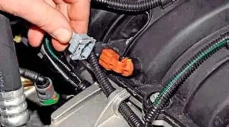
Press on the wire lock of the wire block, disconnect the block from the sensor connector
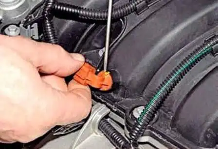
Pry off the sensor flange with a thin slotted screwdriver
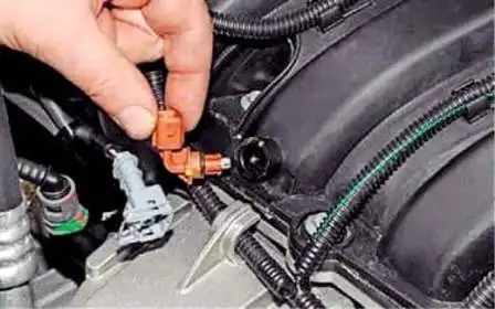
Remove the sensor from the hole in the receiver
Install the sensor in the reverse order. If the rubber ring is damaged, we replace it.
Insert the sensor into the hole of the receiver until the sensor locks click into place.
Replacing the coolant temperature sensor
The sensor is installed in the thermostat housing. Usually, in case of failure, we replace the sensor with a new one.
It is not necessary to drain the engine coolant to replace the sensor.
It is necessary to immediately screw in a new sensor instead of the old sensor.

Remove the air intake and engine air path resonator
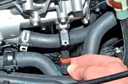
Disconnect the wiring harness from the sensor connector
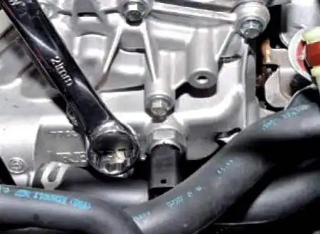
Using a 21 spanner, unscrew the sensor from the hole in the thermostat housing
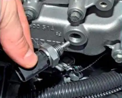
The sensor with the thermostat housing is sealed with an aluminum gasket
We install the sensor and tighten it with a torque of 33 Nm. If necessary, add coolant.
Replacing oxygen concentration sensors
We replace sensors in case of failure and when replacing the exhaust system.
Replacing the control oxygen concentration sensor
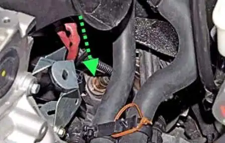
The location of the sensor is shown in the figure
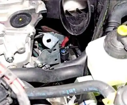
Sensor wiring harness attached to plastic bracket holder
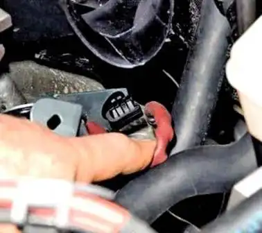
We remove the sensor wiring harness from the plastic bracket attached to the bracket
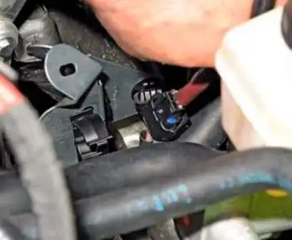
Push the holder latch and slide the sensor wire block down from the holder
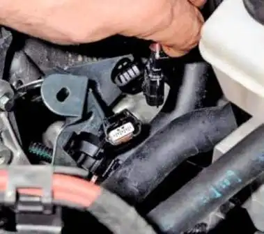
Press the lock of the block and disconnect the block of wires of the control oxygen sensor
We put the wire with the block through the ring of the ring z-shaped key by 22 and unscrew the sensor
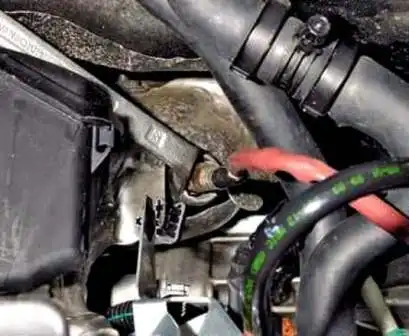
If it is not possible to unscrew the sensor in this way, then remove the receiver and the air filter housing.
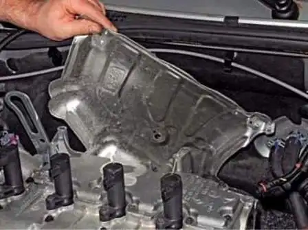
Remove the upper exhaust manifold heat shield
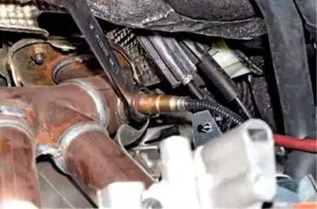
We pass the sensor wire block through the key ring and put it on the sensor hexagon
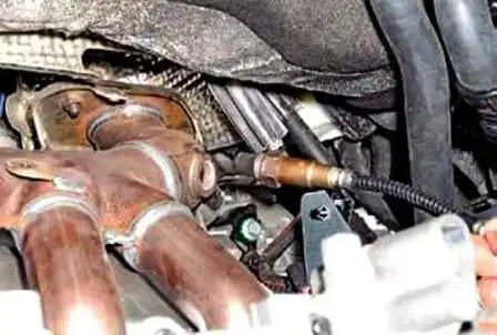
Unscrew the sensor from the exhaust manifold hole
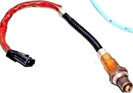
Install the sensor in reverse order
Before installing the sensor, apply graphite grease to the threaded part of the sensor.
Tighten the sensor with a torque of 45 Nm.
Replacing the diagnostic oxygen sensor
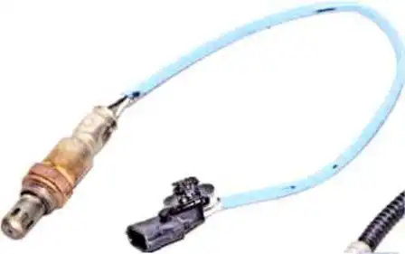
We install the car on a viewing ditch or a lift.
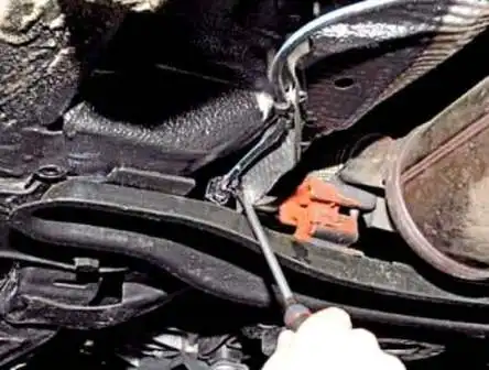
Pry off the holder of the sensor wire block with a flat screwdriver and remove the holder from the hole of the heat shield
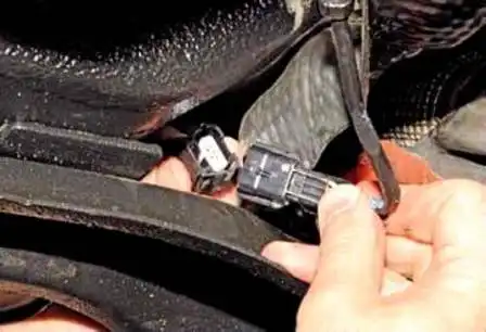
Push the block lock and disconnect the block from the engine control system wire connector
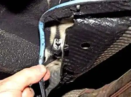
Remove the sensor harness from the holder attached to the body
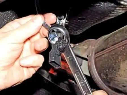
We pass through the ring wrench to the 22 block of the sensor wiring harness
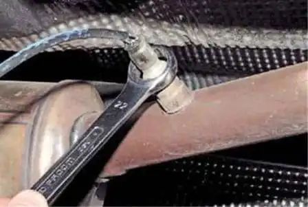
We put the key ring on the sensor hexagon
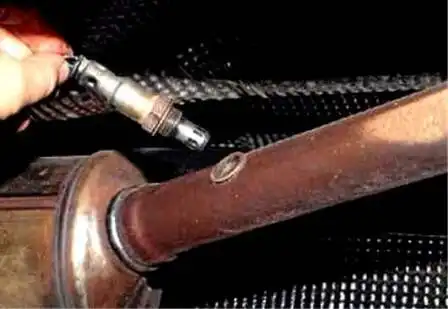
Unscrew the sensor from the hole in the exhaust pipe
Install the diagnostic sensor in reverse order. Apply a thin layer of graphite grease to the threaded part of the sensor and tighten with a torque of 45 Nm.
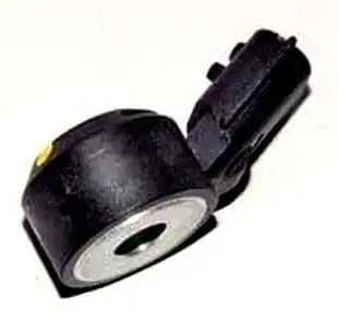
Replacing the knock sensor
We remove the sensor for replacement, as well as when repairing the engine.
An engine knock sensor attached to the cylinder block between cylinders 2 and 3.
It picks up knocks in the engine.
If the car has a 2.0L engine
Removing the protection of the fuel rail (removing the protection is described in the article - Removing the radiator fan engine cooling Renault Duster)
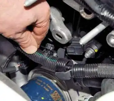
Remove the holder of the generator wiring harness from the hole in the engine bracket
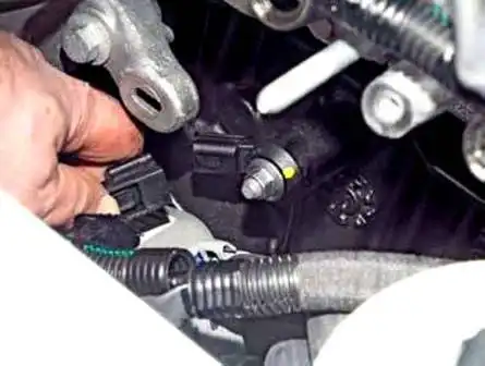
Press the latch and disconnect the wire block from the sensor connector
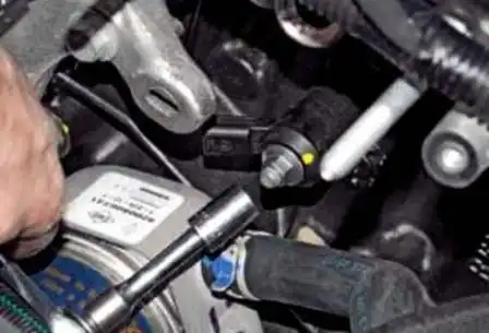
With a 10 head, unscrew the sensor mounting nut
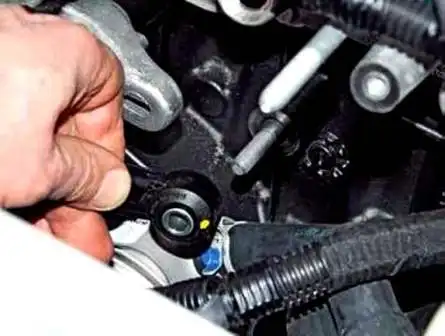
Remove the knock sensor from the cylinder block stud
Before installing the sensor, clean the sensor mounting surface and install the sensor and all parts in reverse order.
If a K4M engine is installed
Remove the fuel rail and remove the oil level dipstick
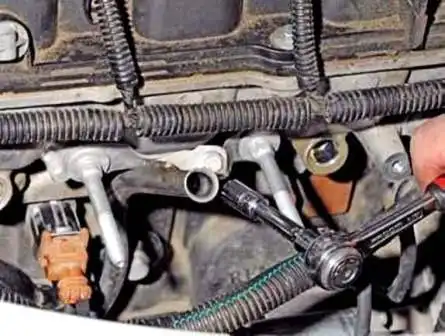
With a head of 8, unscrew the bolt of the guide tube of the oil level indicator
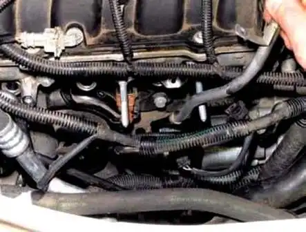
Remove the guide tube from the hole in the cylinder block
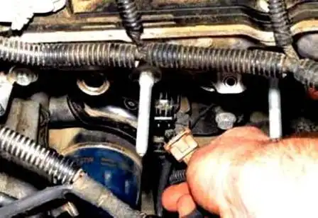
By pressing the latch, disconnect the wire block from the sensor connector
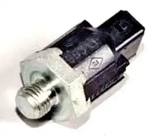
With a high head of 24, we unscrew the sensor from the hole in the cylinder block
Install the sensor in reverse order
Removing the accelerator pedal module
Remove the gas pedal module for replacement
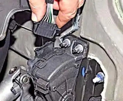
Squeeze the clamp of the wire block and remove the block from the module connector
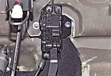
With a 10 head, unscrew the three nuts securing the pedal module to the bulkhead
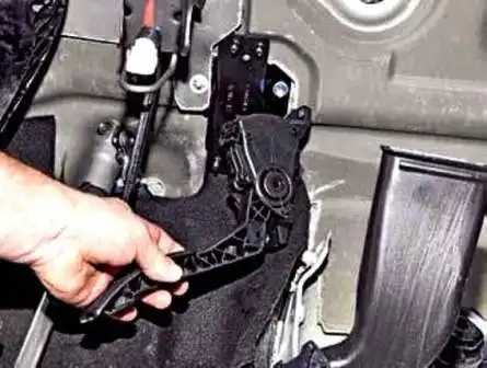
Remove the module
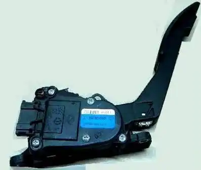
Installing the gas pedal
Removing the clutch pedal position sensor
We remove the sensor when removing the pedal assembly, as well as for replacement.
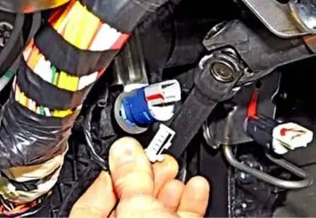
Disconnect the shoe from the clutch pedal position sensor connector
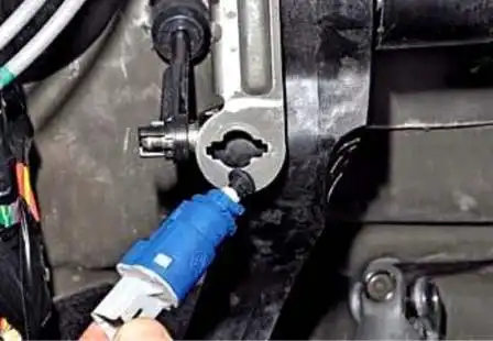
Turn the sensor counterclockwise, remove it from the hole in the pedal assembly bracket
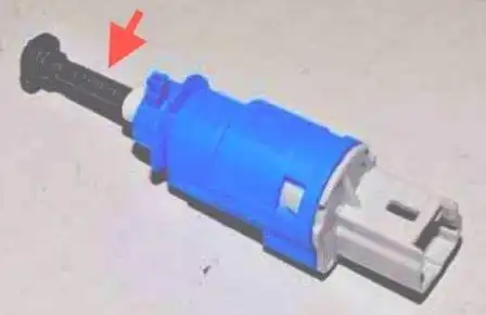
Before installing the sensor, we extend the tip from its body
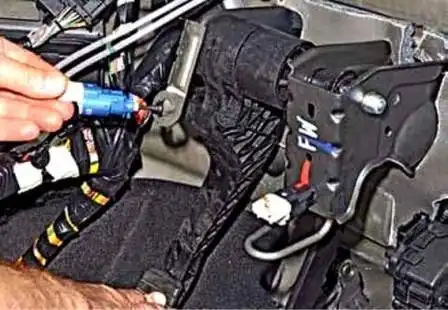
We press the clutch pedal, insert the sensor into the hole in the pedal assembly bracket.
Turn the sensor clockwise, fix it in the bracket hole
Slowly release the clutch pedal.
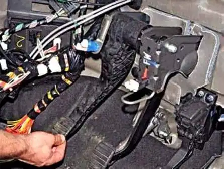
In this case, the clutch pedal buffer will sink the sensor tip into its housing to the required depth.
Removing the brake light switch
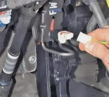
Disconnect the block from the brake light switch connector
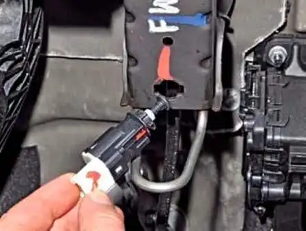
Turn the switch counterclockwise and remove it
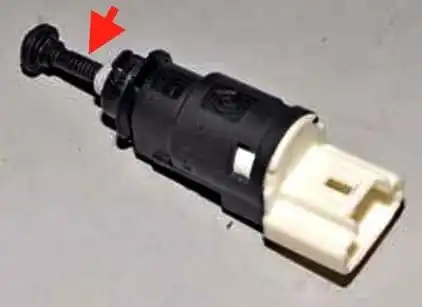
Before installation, we extend the tip of the switch from its body
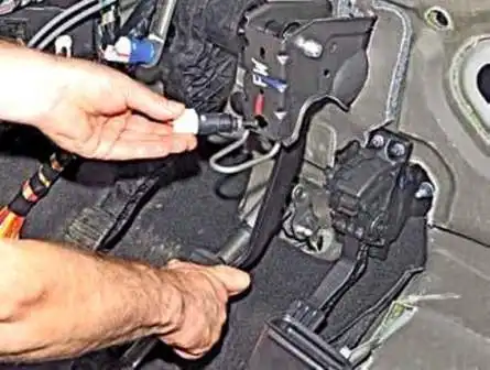
We press the brake pedal, insert the switch into the hole in the pedal assembly bracket.
Turn the switch clockwise and fix it in the bracket hole
Slowly release the brake pedal, while the pedal buffer will sink the tip of the switch by the desired amount.


