
Engines installed on Renault Duster vehicles are equipped with an electronic engine management system with multiport fuel injection
This system ensures that the latest emissions and fumes regulations are met while maintaining high driving performance and low fuel consumption.
The control device in the system is the electronic control unit (ECU).
Based on the information received from the sensors, the ECU calculates the parameters for fuel injection control and ignition timing control.
In addition, in accordance with the embedded algorithm, the ECU controls the operation of the electric motor of the fan of the engine cooling system and the electromagnetic clutch for turning on the air conditioning compressor, performs the function of self-diagnostics of the system elements and notifies the driver of any malfunctions.
If individual sensors and actuators fail, the ECU turns on emergency modes that ensure engine performance.
The amount of fuel supplied by the injectors is determined by the duration of the electrical signal from the ECU.
The electronic unit monitors data on the state of the engine, calculates the need for fuel and determines the required duration of fuel supply by the injectors (signal duration).
To increase the amount of fuel supplied, the duration of the signal increases, and to decrease the amount of fuel, it decreases.
The engine management system, along with the electronic control unit, includes sensors, actuators, connectors and fuses.

Electronic control unit
- (ECU, controller) is connected by electrical wires to all sensors of the system.
Receiving information from them, the block performs calculations in accordance with the parameters and control algorithm stored in the memory of the programmable read-only memory (PROM), and controls the system's executive devices.
The program variant recorded in the PROM memory is indicated by the number assigned to this ECU modification.
The control unit detects a fault, identifies and remembers its code, even if the fault is unstable and disappears (for example, due to poor contact).
The engine control system malfunction indicator in the instrument cluster goes out 10 seconds after the failed unit is restored.
After repair, the fault code stored in the memory of the control unit must be erased.
To do this, turn off the power supply of the unit for 10 s (remove the fuse of the power supply circuit of the electronic control unit or disconnect the wire from the “minus battery” terminal).
The unit supplies DC voltage of 5 and 12 V to various sensors and switches of the control system.
Because the electrical resistance of the power circuits is high, the test lamp connected to the system outputs does not light up.
To determine the supply voltage at the computer terminals, use a voltmeter with an internal resistance of at least 10 MΩ.
The electronic control unit controls the immobilizer system. The ECU is not repairable, so if it fails, it must be replaced.
The number and brand of electronic components of the engine management system depends on the configuration of the car, which power plant is on the car.
Schemes of K4M and F4R engine control systems are presented at the end of the article.
The crankshaft position sensor is designed to synchronize the operation of the electronic engine control unit with the angular position of the crankshaft.
The action of the sensor is based on the Hall effect.

In figure 2, the K4M engine crankshaft sensor

In figure 3, the crankshaft position sensor with the F4R engine
The sensor is installed in the front of the clutch housing above the master ring on the flywheel.
The driving ring is a gear wheel.
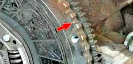
As the crankshaft rotates, the flywheel teeth change the sensor's magnetic field, inducing AC voltage pulses.
The control unit determines the crankshaft speed using the sensor signals and sends pulses to the injectors.
If the sensor fails, the engine cannot be started.
The camshaft position sensor (phase) (only on the F4R engine) is an inductive type mounted at the rear of the cylinder head.

As the intake camshaft rotates, the protrusions on its front journal change the magnetic field of the sensor, inducing AC voltage pulses.
Sensor signals are used by the ECU to organize phased fuel injection in accordance with the order of operation of the cylinders, as well as to control the change in valve timing depending on the engine operating mode.
If a malfunction occurs in the camshaft position sensor circuit, the electronic unit memorizes its code and turns on the warning light.
The coolant temperature sensor is installed in the water distributor housing of the engine cooling system.

The sensing element of the sensor is a thermistor, the electrical resistance of which changes inversely with temperature.
At a low coolant temperature (-20 °C), the resistance of the thermistor is about 15 kOhm, when the temperature rises to +80 °C, the resistance decreases to 320 Ohm.
The electronic unit supplies the temperature sensor circuit with a constant "reference voltage.
The voltage of the sensor signal reaches its maximum value on a cold engine and decreases as it warms up.
The electronic unit determines the engine temperature from the voltage value and takes it into account when calculating the injection and ignition control parameters.
If the sensor fails or there are violations in its connection circuit, the ECU sets the fault code and remembers it.
An additional thermistor is also installed in the sensor housing to control the coolant temperature gauge in the instrument cluster.
Throttle position sensor installed only on the K4M engine.

The throttle position sensor is mounted on the throttle body and is connected to the throttle valve axis.
The sensor is a potentiometer, one end of which is supplied with a "plus supply voltage (5 V), and the other end is connected to the ground."
The third output of the potentiometer (from the slider) is the output signal to the electronic control unit.
When the throttle valve is turned (from the action on the control pedal), the voltage at the output of the sensor changes.
When the throttle is closed, it is lower than 0.5 V. When the throttle opens, the voltage at the sensor output rises, when the throttle is fully open, it should be more than 4 V.
By monitoring the output voltage of the sensor, the ECU adjusts the fuel supply depending on the throttle opening angle (i.e. at the request of the driver).
The throttle position sensor does not require adjustment, as the control unit perceives idling (i.e. full throttle closing) as a zero mark.
The oxygen concentration control sensor is used in the feedback injection system and is installed on the exhaust manifold.

Information about the presence of oxygen in the exhaust gases is used to correct the calculations of the duration of the injection pulses.
The oxygen contained in the exhaust gases reacts with the sensor, creating a potential difference at the sensor output.
It varies from approximately 0.1V (high oxygen - lean) to 1V (low oxygen - rich).
Trace By listening to the output voltage of the oxygen concentration sensor, the controller determines which command to adjust the composition of the working mixture to send to the injectors.
If the mixture is lean (low potential difference at the sensor output), then the controller gives a command to enrich the mixture; if the mixture is rich (high potential difference) - to deplete the mixture.
Lambda probe is a vulnerable sensor in a car's injection system.
Its resource is from 20 to 80 thousand km, depending on the quality of gasoline and engine oil, operating conditions.
According to the recommendation of the factory, it must be changed every 75 thousand km. car mileage.
It is possible to “poison” the sensor electrodes with leaded gasoline over several refuelings.
If the oxygen concentration sensor is faulty, the ECU goes into a mode in which its voltage is not taken into account to determine the parameters of the mixture.
The ECU continues to control the composition of the mixture, taking into account the temperature and parameters of other sensors.
The diagnostic oxygen sensor works on the same principle as the control sensor.
The signal generated by the diagnostic oxygen sensor indicates the presence of oxygen in the exhaust gases after the converter.
If the converter is working properly, the readings of the diagnostic sensor will differ significantly from the readings of the control sensor.
The
Knock Sensor is attached to the side of the cylinder block in the area between the 2nd and 3rd cylinders and detects abnormal vibrations (knock) in the engine.

The sensing element of the knock sensor is a piezoelectric plate.
During detonation, voltage pulses are generated at the output of the sensor, which increase with increasing intensity of detonation impacts.
The electronic unit, based on the sensor signal, regulates the ignition timing to eliminate detonation fuel flashes.
Vehicle speed sensor

In the process, the ECU also uses the vehicle speed data received from the speed sensor.
The sensor is mounted on the gearbox.
The principle of operation of the sensor is based on the Hall effect.
The sensor sends rectangular voltage pulses to the electronic control unit with a frequency proportional to the speed of rotation of the drive wheels.
An absolute pressure sensor in the receiver converts the degree of vacuum in the receiver to a change in electrical voltage, according to the value of which the ECU sets the parameters of the engine.
The sensor is installed on the receiver.

The output voltage of the sensor changes according to the pressure in the intake pipe - from 4.0 V (at wide open throttle) to 0.79 V (at closed throttle).
When the engine is not running, the control unit determines the atmospheric pressure from the sensor voltage and adapts the injection control parameters to the specific altitude.
Atmospheric pressure values stored in the memory are periodically updated when the vehicle is in steady motion and during full throttle opening.
The solenoid valve of the variable valve timing system (only on the F4R engine) is installed in the engine cylinder head.

The valve regulates the oil pressure supplied to the timing actuator mounted on the forward end of the intake camshaft.
The system performs optimal tuning of the valve timing, changing them over the entire range of engine frequency and load, which increases power and torque at any speed.
When the engine is stopped, oil pressure causes the control valve spool to move to the position corresponding to the latest valve timing.
The control valve is actuated by the block signal ka engine control and supplies oil either to the lag chamber or to the advance chamber with a continuous change in the valve timing, respectively, either in the direction of their advance or in the direction of delay.
The intake manifold air temperature sensor is the same design as the coolant temperature sensor.

It also uses a thermistor whose resistance changes with temperature. The ECU constantly supplies voltage to the sensor.
The signal voltage of the sensor is maximum when the air in the intake pipe is cold, and decreases as its temperature rises.
According to the voltage value, the unit makes adjustments when calculating the ignition timing.
Also, to maintain optimal engine operating conditions under different conditions, the ECU uses signals from the clutch pedal position sensor (vehicle with a manual transmission) or automatic transmission sensors, brake light switch, wheel speed sensors (ABS).

Using the signals from the clutch pedal position sensor and the brake light switch, the ECU distinguishes between depressed and not depressed positions of the pedals.
When the clutch pedal is depressed, the ECU limits the fuel supply to the cylinders.
Diagnostic connector is used to display fault codes from the ECU memory detected during the operation of the engine management system.

It is located in the salon, in a glove box on its back wall.
The following main parameters of engine operation are read through this connector:
- — fuel correction system operation mode;
- — calculated load on the engine;
- — coolant temperature;
- — fuel pressure in the fuel system;
- - air pressure in the intake pipe;
- - engine speed;
- — vehicle speed (in motion - with a portable scanning device connected);
- — ignition advance angle;
- — intake air temperature;
- — air flow;
- — throttle position;
- — data from oxygen sensors.
Before removing any components of the fuel injection control system, disconnect the wire from the negative terminal of the battery.
Do not start the engine if the cable lugs on the battery are loose.
Never disconnect the battery from the vehicle's electrical system while the engine is running.
When charging the battery, disconnect it from the car's on-board network.
Do not expose the ECU to temperatures above 65 ˚C in working condition and above 80 °C in non-working condition (for example, in a drying chamber).
Do not disconnect or connect wires to the computer while the ignition is on.
Before carrying out electric welding work on the car, disconnect the wires from the battery and the wiring harness pads from the computer.
Perform all voltage measurements with a digital voltmeter with an internal resistance of at least 10 MΩ.
Electronic components used in the fuel injection system are designed for very low voltage, so they can be easily damaged by electrostatic discharge.
To prevent damage to the ECU, do not touch the terminals with your hands.

Scheme of the K4M engine control system is shown in Figure 16.

Scheme of the F4R engine control system is shown in Figure 17

")
")
")
")
")
")
")
")