


We replace the belt every 60,000 km of vehicle mileage or four calendar years of service life.
At every service, the condition of the belt must be checked.
The auxiliary drive layout depends on the vehicle's configuration: whether or not air conditioning is fitted to the vehicle.
The belt tension is adjusted by an automatic tensioner.
To check and replace the belt, we place the vehicle on an inspection pit or a lift.
We place chocks under the rear wheels.
We apply the parking brake. We loosen the bolts of the front right wheel.
We raise the front of the vehicle and remove the front right wheel.
We remove the engine compartment mudshield (article — Removal of engine protection, wheel arch liners and mudflaps).
We undo the three screws securing the right wheel arch liner to the front bumper and one screw securing the wheel arch liner to the wing.
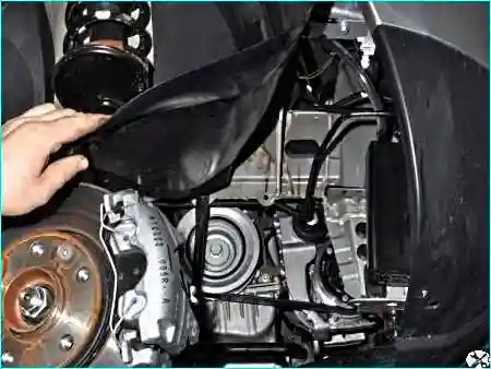
We bend back the front part of the wheel arch liner and tuck it behind the brake mechanism disc.
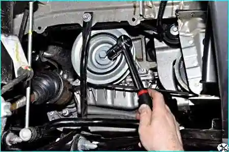
Using an 18 mm socket, we turn the crankshaft by the auxiliary drive pulley securing bolt clockwise and inspect the belt along its entire length. If cracks or other defects are found on the belt, we replace it.
Replacing the rollers and the auxiliary drive belt on the 2.0 l engine
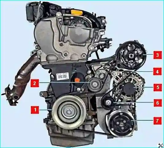
The belt installation layout is shown in figure 3.
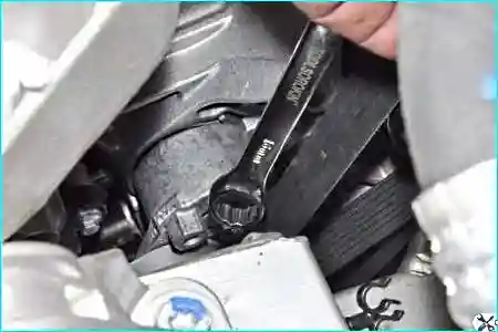
We fit a 16 mm ring spanner onto the hexagon of the tensioner and turn the roller bracket clockwise.
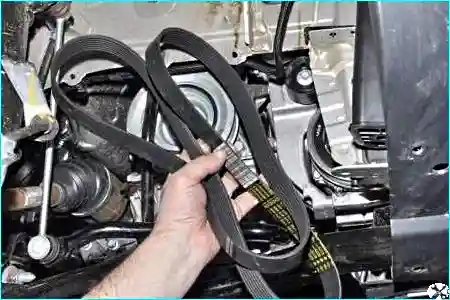
We remove the belt from the pulleys and take it out of the engine compartment.
Marking of the auxiliary drive belt with air conditioning 7PK 1792.
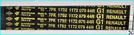
Belt length 1792 mm.
To replace the belt support roller:
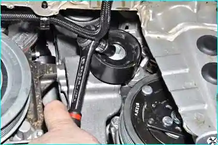
Using a 13 mm socket, we undo the roller securing bolt.
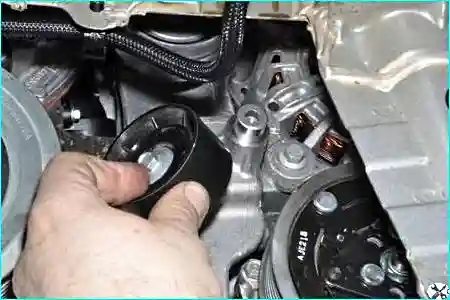
We remove the roller with its securing bolt.
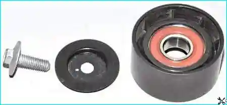
We withdraw the bolt and the roller cover from the roller.
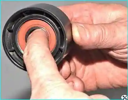
By turning the roller, we determine the condition of the bearing.
The roller should turn silently, evenly, without jamming.
To replace the tensioner roller:
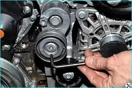
Using a Torx T40 key, we undo the roller securing screw.
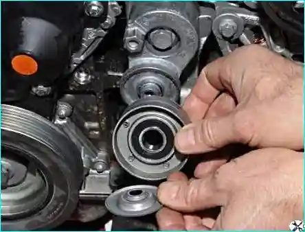
We remove the tensioner roller and the roller cover.
If necessary, we remove the tensioner; to do this:
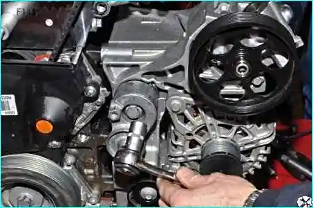
Using a 16 mm socket, we undo the tensioner securing bolt.
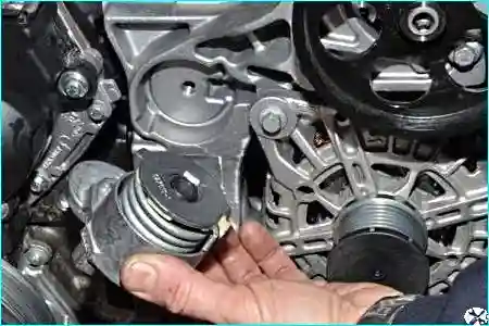
We remove the tensioner with the roller.
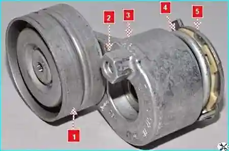
When fitting the tensioner, lug 1 on the tensioner must enter slot 2 in the auxiliary drive mounting bracket.
We install all parts in the reverse order. We install the belt in accordance with the layout in figure 3.
Replacing the rollers and the auxiliary drive belt on the 1.6 l engine
Marking of the auxiliary drive belt for the K4M engine 6PK 1822 with air conditioning.
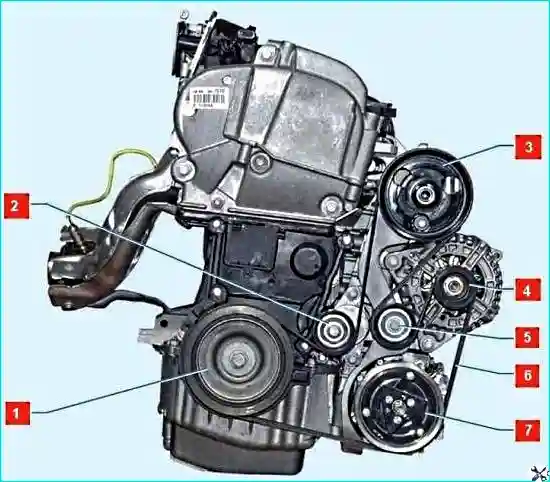
We release the belt tension; from underneath the vehicle, we fit a 15 mm spanner or a 15 mm socket onto the tensioner roller securing bolt.
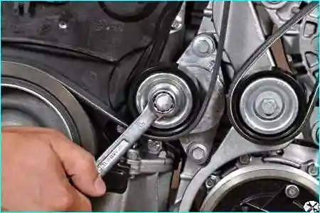
We turn the roller bracket clockwise and release the belt.
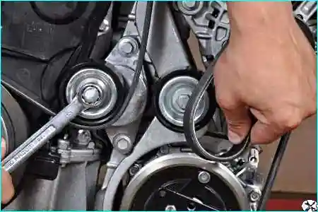
We remove the belt from the support roller.
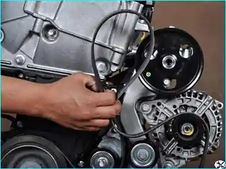
We remove the auxiliary drive belt from the pulleys.
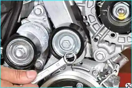
To remove the support roller, we undo its securing bolt with a ring spanner.
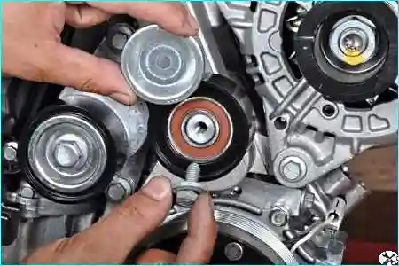
We remove the outer roller cover.
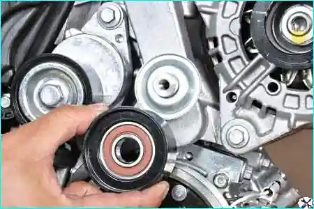
We remove the support roller.
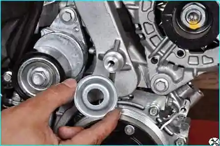
We remove the inner cover.
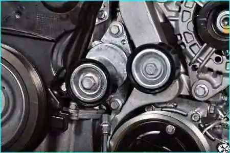
To remove the tensioner, using a 10 mm socket, we undo two bolts.
We remove the tensioner with the roller.
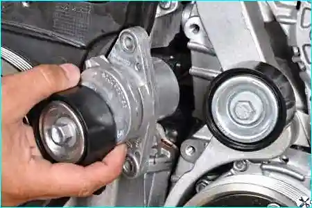
We install all parts in the reverse order.
We lay the belt on the pulleys and route it under the tensioner and support rollers in accordance with the layout.


