Renault Duster cars are equipped with engines of two modifications: K4M with a volume of 1.6 liters and F4R with a volume of 2.0 liters.
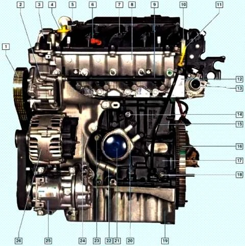
F4R engine (front view in the direction of vehicle movement): 1 - auxiliary drive belt; 2 - power steering pump; 3 - timing belt; 4 - oil filler cap; 5-sensor of absolute air pressure; 6 - intake air temperature sensor; 7- receiver; 8 - inlet pipeline; 9 - fuel rail with injectors; 10- cylinder head cover; 11 - oil level indicator; 12 - cylinder head; 13 - thermostat; 14 - knock sensor; 15 - guide oil level indicator; 16 - flywheel; 17 - cylinder block; 18 - cork; 19 - oil pan; 20 - heat exchanger; 21 - oil filter; 22 - inlet pipe of the coolant pump; 23 - low oil pressure indicator sensor; 24 - bracket for auxiliary units; 25 - air conditioning compressor; 26 - generator
Both engines are gasoline, four-stroke, four-cylinder, in-line, sixteen-valve - with an overhead camshaft.
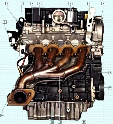
F4R engine; 1 - coolant temperature sensor; 2 - cylinder head; 3 - left eye; 4 - cylinder head cover; 5 - receiver; 6 - throttle assembly; 7 - right eye; 8 - top cover of the timing drive; 9 - lower timing cover; 10 - auxiliary drive belt; 12 - exhaust manifold; 13 - oil pan; 14 - control oxygen concentration sensor
The engines are located transversely in the engine compartment.
The engines are similar in design. The main differences are related to the size of the parts.
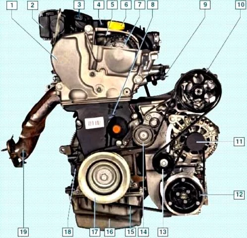
F4R engine (right view); 1 - top cover of the timing drive; 2 - throttle assembly; 3 - absolute air pressure sensor; 4 - receiver; 5 - timing belt; 6 - oil filler cap; 7 - phase regulator; 8 - lower cover of the timing drive; 9 - fuel rail; 10 - power steering pump pulley; 11 - generator pulley; 12 - electromagnetic clutch of the air conditioning compressor; 13 - roller supporting the belt of auxiliary units; 14 - belt tensioner roller; 15 - auxiliary drive belt; 16 oil pan; 17 - auxiliary drive pulley; 18 - cylinder block; 19 exhaust manifold
Cylinder firing order: 1-3-4-2, counting from the flywheel.
The power system is sequential multi-flow fuel injection.
An engine with a gearbox and a clutch form a power unit mounted on three rubber-metal bearings.
The engine power system consists of an electric fuel pump installed in the fuel tank, a throttle assembly, a fine fuel filter, a coarse fuel filter located in the fuel pump module, a fuel pressure regulator, injectors, fuel lines, an exhaust gas recirculation system and an air filter.
The engine ignition system is microprocessor-based and consists of coils and spark plugs.
The electronic unit (controller) of the engine management system controls the ignition coils.
The ignition system does not require maintenance and adjustment during operation.
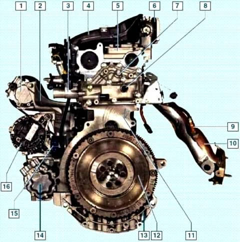
F4R engine (left view in vehicle direction); 1 - hydraulic power steering pump; 2 - bracket for auxiliary units; 3 - thermostat cover; 4 - receiver; 5 - cylinder head cover; 6 - throttle assembly; 7 - thermostat housing; 8 - coolant temperature sensor; 9 - control oxygen concentration sensor; 10 - exhaust manifold; 11 - cylinder block; 12 - flywheel; 13 - oil pan; 14 - air conditioning compressor; 15 - oil filter; 16 - generator
The F4R motor uses a phase control circuit using a phase regulator. The phase regulator regulates the moment of opening the engine intake valves.
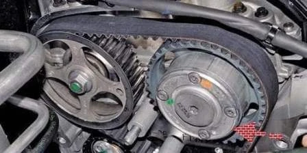
The system ensures the installation of optimal valve timing for each moment of engine operation in order to increase its power and dynamic characteristics by changing the position of the intake camshaft.
The electronic engine control unit (ECU) controls the system.
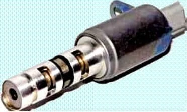
The main elements of the phase control system include a control solenoid valve, an actuator for changing the position of the camshaft and a camshaft position sensor.
The timing belt drives the system's actuator, which transmits rotation to the intake camshaft through hydromechanical coupling.
From the main oil line through the channels, engine oil is supplied under pressure to the seat of the cylinder head, in which the valve is installed, and then through the channels in the head and in the camshaft to the system actuator.
In the initial position and at an engine speed of up to 1450 min-1, power is not supplied to the solenoid valve - it is closed.
When the crankshaft speed is in the range of 1450-4300 min-1 and with the gas pedal fully depressed, the computer supplies power to the solenoid valve - it opens.
At the same time, the spool device of the valve ensures the supply of oil under pressure to the working cavity of the actuator.
Due to a change in oil pressure and hydromechanical action, the individual elements of the actuator are mutually moved, and the camshaft rotates to the required angle, changing the valve timing.
When the crankshaft speed is higher than 4300 min-1, the power supply to the solenoid valve stops.
The solenoid valve spool and system actuator components are very sensitive to engine oil contamination.
When the phase change system fails, the inlet valves open and close in the maximum delay mode.
The variable valve timing system allows you to set the optimal valve timing for every moment of engine operation, resulting in increased power, better fuel efficiency and less exhaust emissions.
To determine the instantaneous position of the camshaft, a camshaft position sensor (phase sensor) is installed.
The position sensor ring is located on the camshaft journal.
A solenoid valve is fixed on the top cover of the timing mechanism drive, hydraulically controlling the mechanism for changing the valve timing.
The solenoid valve, in turn, is controlled by the electronic engine control unit.
The control unit determines the position of the intake camshaft from the signals of the phase sensor and the crankshaft position sensor and issues a command to change the position of the shaft.
In accordance with this command, the spool of the solenoid valve is moved, for example, in the direction of more advanced opening of the intake valves.
In this case, the pressurized oil enters through the channel in the valve body into the valve body and causes the camshaft to rotate in the required direction.
When moving the spool in the direction that corresponds to the earlier opening of the valves, the channel for their later opening is automatically connected to the drain channel.
If the camshaft has rotated to the required angle, the solenoid valve spool, at the command of the control unit, is set to a position in which oil is maintained under pressure on both sides of each of the clutch rotor blades.
If it is required to turn the camshaft towards a later opening of the valves, the control process is carried out with oil supply in the opposite direction.
When the engine is stopped, the intake camshaft is automatically set to its original position, in which there is no overlap between the phases of the intake and exhaust valves.
This is done to ensure a reliable start of a cold engine.
With this The arrangement of the phases excludes the dilution of the fresh air-fuel charge entering the cylinder during the intake stroke with the exhaust gases.
In addition to making it easier to start the engine, this ensures its smooth and uninterrupted operation during warm-up.
As the engine warms up, the valve timing changes smoothly until they overlap on a fully warm engine, which ensures its best efficiency.
The elements of the variable valve timing system (the solenoid valve and the mechanism for dynamically changing the relative position of the camshafts) are precision-made components.
In this regard, when performing maintenance or repair of the variable valve timing system, only the replacement of the complete system elements is allowed.
Front on the engine (in the direction of vehicle movement) are: oil level gauge, fuel rail with injectors, intake manifold, oil filter, heat exchanger (engine 2.0), low oil pressure indicator sensor, knock sensor, crankshaft position sensor (2.0 engine), coolant pump feed pipe, starter (1.6 engine), alternator, power steering pump, air conditioning compressor.
At the back of the engine are: throttle assembly, air filter housing, exhaust manifold with a control oxygen concentration sensor, starter (engine 2.0).
The engine cylinder block is cast iron, the cylinders are bored directly in the block.
In the lower part of the cylinder block, there are five crankshaft main bearing supports with removable covers that are bolted to the block.
The bores in the cylinder block for the bearings are machined with the covers installed, so the covers are not interchangeable.
On the end surfaces of support No. 3 of the K4M engine and No. 2 of the F4R engine, sockets are made for thrust half rings that prevent axial movement of the crankshaft.
To cool the pistons during engine operation, their bottoms are washed from below with engine oil through special nozzles that are pressed into the cylinder block.
Crankshaft with five main journals and four crankpins.
The shells of the main and connecting rod bearings of the crankshaft are steel, thin-walled with an anti-friction coating applied to the working surfaces of the shells.
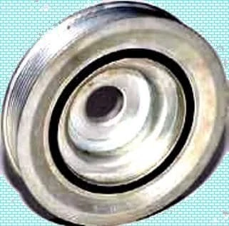
At the front end of the crankshaft are installed: an oil pump drive sprocket, a timing gear pulley and an accessory drive pulley, which is also a crankshaft vibration damper.
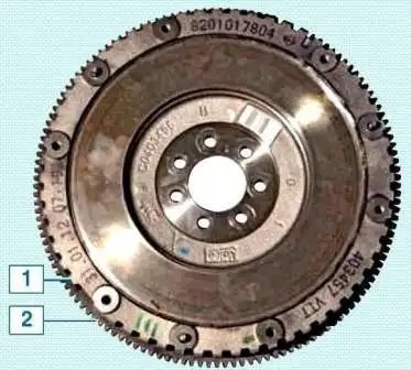
The crankshaft is sealed front and rear with oil seals.
Connecting rods - forged steel, I-section, machined with covers.
The caps are attached to the connecting rods with bolts on the F4R engine and bolts and nuts on the K4M engine.
With their lower (crank) heads, the connecting rods are connected through liners to the connecting rod journals of the crankshaft, and the upper heads are connected through the piston pins to the pistons.
Piston pins are tubular steel.
On the 2.0 engine, the floating pin rotates freely in the piston bosses and the upper connecting rod head.
From axial movement, the pin is fixed by two retaining spring rings located in the grooves of the piston bosses.
On the 1.6 engine, the piston pin is pressed into the upper head of the connecting rod and rotates freely in the piston bosses.
Pistons are made of aluminum alloy.
The piston skirt has a complex shape: the skirt is barrel-shaped in longitudinal section, and oval in transverse section.
Three grooves for piston rings are machined in the upper part of the piston.
The top two piston rings are compression rings, and the bottom one is oil scraper.
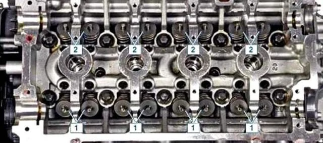
Cylinder head cast from aluminum alloy, common to all four cylinders.
The cylinder head is centered on the block bushings and secured with ten screws.
A non-shrinking metal gasket is installed between the block and the head.
On opposite sides of the cylinder head there are windows for intake and exhaust channels.
Spark plugs are installed in the center of each combustion chamber.
Steel valves, arranged in two rows in the cylinder head, V-shaped, two intake and two exhaust valves for each cylinder.
The inlet valve plate is larger than the outlet valve.
The valve seats and guides are pressed into the cylinder head.
Oil caps are put on top of the valve guides.
The valve closes under the action of a spring.
The lower end rests on the washer, and the upper end rests on the plate, which is held by two crackers.
The folded crackers have the shape of a truncated cone on the outside, and on the inside they are equipped with persistent beads that enter the groove on the valve stem.
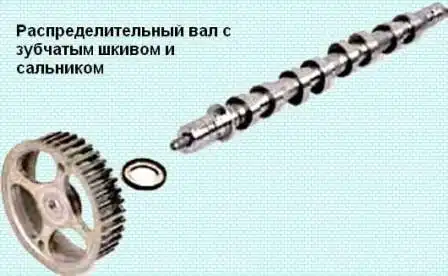
Two camshafts are mounted on top of the cylinder head.
One shaft drives the intake valves of the gas distribution mechanism, and the other drives the exhaust valves.
Eight cams are made on each shaft - an adjacent pair of cams simultaneously controls the valves (inlet or exhaust) of each cylinder.
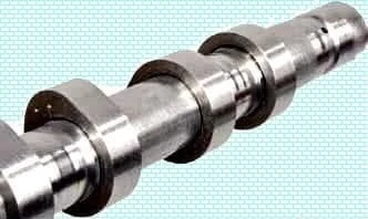
The design feature of the camshaft is that the cams are pressed onto the tubular shaft.
Supports (beds) of camshafts (six bearings for each shaft) are detachable - located in the cylinder head and in the head cover.
Camshaft drive - toothed belt from the crankshaft pulley.
On each camshaft, on the side of the toothed pulley, a thrust flange is made, which enters the groove of the cylinder head, thereby preventing axial movement of the shaft.
The camshaft pulley is not fixed on the shaft with a tight fit, key or pin, but only due to the friction forces that occur on the end surfaces of the pulley and shaft when the pulley fastening nut is tightened.
The toe of the camshaft is sealed with an oil seal, put on the neck of the shaft and pressed into the socket formed by the surfaces of the cylinder head and the head cover.
Valves are driven by camshaft lobes through valve levers.
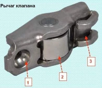
To increase the life of the camshaft and valve levers, the cam of the shaft acts on the lever through a roller rotating on the axis of the lever.
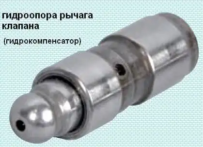
The hydraulic bearings of the valve levers are installed in the sockets of the cylinder head.
The oil inside the hydromount comes from the line in the cylinder head through the hole in the hydromount body.
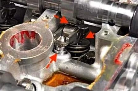
Hydrosupport automatically ensures backlash-free contact of the camshaft cam with the valve lever roller, compensating for wear on the cam, lever, valve stem end, seat chamfers and valve disc.
Engine lubrication - combined.
Under pressure, oil is supplied to the crankshaft main and connecting rod bearings, camshaft bearings and valve lever hydraulic bearings.
Other engine components are splash lubricated.
The pressure in the lubrication system creates gearsth oil pump located in the oil pan and attached to the cylinder block.
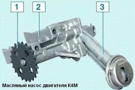
The oil pump is driven by a chain from the crankshaft.
The pump drive sprocket is mounted on the crankshaft under the front cover of the cylinder block.
A cylindrical belt is made on the sprocket, along which the front crankshaft oil seal works.
The sprocket is mounted on the crankshaft without tension and is not fixed with a key.
When assembling the engine, the pump drive drive sprocket is clamped between the timing gear pulley and the crankshaft shoulder as a result of the package of parts being pulled together by the accessory drive pulley mounting bolt.
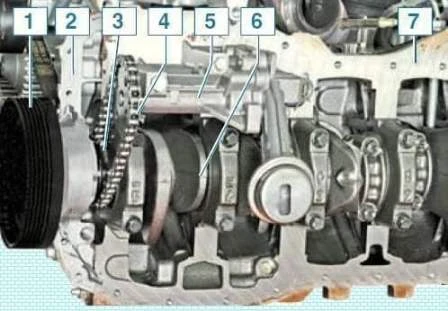
The torque from the crankshaft is transmitted to the sprocket only due to the frictional forces between the end surfaces of the sprocket of the toothed pulley and the crankshaft.
If the accessory drive pulley bolt is loosened, the oil pump drive sprocket may begin to rotate on the crankshaft and the engine oil pressure will drop.
The oil receiver is made in one piece with the cover of the oil pump housing.
The cover is fixed with five screws to the pump body and is kept from falling out by a spring retainer.
Oil from the pump is fed through a channel in the cylinder block to the oil filter.
Oil filter - full flow, non-separable.
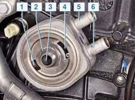
On the F4R engine, before entering the filter, the oil passes through a heat exchanger attached to the cylinder block.
When the engine is running, the cooling system fluid constantly circulates through the heat exchanger cells.
Shortly after starting the engine, the engine oil in the heat exchanger heats up (due to the fact that the coolant heats up faster).
When the engine is running at maximum speed, the oil is cooled in the heat exchanger.
After passing through the oil filter, oil is supplied to the main line of the cylinder block.
From the main line, oil flows through channels to the crankshaft main bearings, piston cooling nozzles, and then to the shaft connecting rod bearings.
Through two vertical channels in the cylinder block, oil from the main line is supplied to the cylinder head - to the extreme supports (from the side of the camshaft plugs) of the shafts and valve hydraulic supports.
Through the grooves and drillings in the extreme bearing journals of the camshafts, oil enters the shafts, and through the drillings in other shaft sheikhs - to other camshaft bearings.
From the cylinder head, oil flows through vertical channels into the oil pan.
Crankcase ventilation system - closed, forced type.
Gases that have penetrated from the combustion chambers of the cylinders through the piston rings into the crankcase of the engine enter through the channels in the block and the cylinder head into the head cover.
After passing through the oil separator located in the cylinder head cover, crankcase gases are cleaned of oil particles and then flow through the air filter housing, throttle assembly, receiver and inlet pipeline into the engine cylinders.
Possible engine malfunctions
Cause of malfunction / Remedy
Engine won't start. No fuel pressure in rail:
- - Clogged fuel lines - Flush and blow out the fuel tank and fuel lines
- - Faulty fuel pump - Replace pump Renault Duster Fuel Module Repair
- - Clogged fuel filter - Replace the filter Replacing the optional Renault Duster fuel filter
- - Faulty fuel pressure regulator - Replace pressure regulator
- - Faulty ignition system - Diagnose the engine management system
The engine does not develop full power and does not have sufficient throttle response:
- - Faulty throttle position sensor - Replace Throttle Assembly How to Remove Renault Duster Throttle Assembly
- - Insufficient pressure in the fuel rail - See above
- - Air filter dirty - Replace filter element
- - Faulty ignition system - Diagnose the engine management system
Insufficient compression - below 10 kg/cm2:
- - Broken cylinder head gasket - Replace the gasket Replacing a Renault Duster cylinder head gasket
- - Burnout of pistons, breakage or occurrence of piston rings - Clean the rings and piston grooves from carbon deposits, replace the rings
- - Poor fit of valves to seats - Replace damaged valves, grind seats
- - Excessive wear of cylinders and piston rings - Replace pistons, bore and refinish cylinders
Engine runs erratically or stalls at idle:
- - Insufficient pressure in the fuel rail - See above
- - Air suction through a hose connecting the receiver to the vacuum brake booster - Tighten the clamps, replace the damaged hose
- - Faulty ignition system - Diagnose the engine management system
Insufficient oil pressure in a warm engine:
- - Poor oil quality - Change the oil Changing Renault Duster engine oil and filter
- - Dilution or foaming of oil due to penetration of fuel or coolant into the crankcase - Remove causes and change oil
- - Contamination of the working cavity or wear of the oil pump parts - Flush or repair the oil pump
- - Clogged oil filter - Change the oil filter
- - Loose fastening or clogging of the oil receiver - Wash or repair the oil receiver
- - Increased clearance between the main and connecting rod bearing shells and the crankshaft journals - Sand the necks and replace the liners
Knock of crankshaft main bearings:
Usually dull tone, metallic sound
Detected when the gas pedal is pressed hard
Its frequency increases with increasing crankshaft speed.
Excessive axial clearance of the crankshaft causes sharper, uneven gaps, especially noticeable with a smooth increase or decrease in the crankshaft speed
- - Insufficient oil pressure - See fault - insufficient oil pressure
- - Increased clearance between the thrust flanges of the middle main bearing shells and the crankshaft - Replace the half rings with new ones, check the clearance
Rattle of connecting rod bearings:
The sound of connecting rod bearings is sharper than the sound of main bearings.
The knock is heard at idle, with a sharp opening of the throttle.
The place of knocking is easy to determine by turning off the spark plugs in turn
- - Increased clearance between the connecting rod journals of the crankshaft and liners - Replace the liners and grind the crankshaft journals
The sound of pistons:
The knock is unvoiced, muffled, caused by the beating of the piston in the cylinder.
Better audible at low engine speeds and under load
- - Increased clearance between pistons and cylinders - Replace pistons, bore and refinish cylinders
- - Excessive clearance between piston rings and grooves on the piston - Replace rings or pistons with rings
Increased noise of the gas distribution mechanism:
- - Reduced oil pressure in the lubrication system - See fault "Insufficient oil pressure"
- - Camshaft lobes wear - Replace the camshaft
Knocking on a cold engine:
- - audible within two to three minutes after starting and intensifying with increasing speed to crankshaft:
- - Increased clearance between pistons and cylinders
Piston knocking that disappears after the engine warms up, which is not a sign of a malfunction.
In case of constant knocking, replace the pistons, bore and hone the cylinders
- - Loosening of the crankshaft pulley - Tighten the mount
Short-term knocks immediately after starting the engine:
- - Use of substandard oil with reduced viscosity - Change the oil
- - Increased axial clearance of the crankshaft - Replace thrust washers
- - Increased clearance in the front main bearing - Replace front main bearing shells
Knocking in a warm engine at idle:
- - Loose or worn accessory drive belt - Change the belt
Noise of parts of the gas distribution mechanism:
See "timing failure"
- - Using substandard oil - Change the oil
- - Increased clearances between the piston pins and the holes in the piston bosses - Replace pistons and pins
- - The axes of the upper and lower connecting rod heads are not parallel - Replace connecting rod
Strong knocks in a warm engine at an increased frequency of the crankshaft:
- - The auxiliary drive belt is too tight or cracks and breaks appear on it - Replace the damaged belt Checking and replacing the Renault Duster accessory belt
- - Loose flywheel mounting - Tighten the flywheel bolts to the correct torque
Increased engine vibration:
- - Crankshaft imbalance - Remove and balance the crankshaft
- - Unequal compression values in cylinders - Fix the cause of insufficient compression
- - The suspension bearings of the power unit are heavily worn out - Replace powertrain mounts
Engine knocking when under load:
- - Use of low octane gasoline - Change gasoline
Increased oil consumption:
- - Oil leakage through engine seals - Tighten fasteners or replace gaskets
- - Clogged crankcase ventilation system - Clean the parts of the crankcase ventilation system
- - Engine piston ring wear - Replace pistons and rings
- - Broken piston rings - Replace rings
- - Coking of oil scraper rings or grooves in the piston grooves due to the use of substandard oil - Change the engine oil, clean the rings and grooves from carbon deposits
- - Wear or damage to valve stem seals - Replace valve stem seals Replacement of Renault Duster valve stem seals
- - Increased wear of valve stems or guide bushings - Replace valves, repair cylinder heads
Engine overheating:
- - Insufficient amount of fluid in the cooling system - Add coolant to the cooling system
- - The outer surface of the radiator is heavily soiled - Clean the outer surface of the radiator with a jet of water
- - Faulty thermostat - Replace thermostat Removing thermostat and thermostat housing Renault Duster
- - Faulty electric fan of the cooling system - Check the fan motor, fan switch sensor and relay, replace faulty parts
- - The valve plug of the expansion tank of the cooling system is faulty - Replace expansion tank cap
- - Use of gasoline with a lower octane rating - Change gasoline
Quick drop in the liquid level in the expansion tank:
- - Radiator damaged - Repair or replace the radiator
- - Damage to hoses or gaskets in connections - Replace damaged hoses and gaskets
- - Liquid leakage through microcracks in the cylinder block or cylinder head - Check the tightness of the block and cylinder head


