In the article, we will consider checking and replacing parts and assemblies of the oil system of the Cummins ISF3.8 engine
Checking oil pressure
Remove the plug from the oil pressure test port located in the oil filter cap.
Install the pressure gauge.
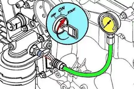
Warm up the engine to operating temperature.
Check the oil pressure at minimum speed.
At minimum speed 69 kPa
Increase the engine speed to the nominal speed and let it run in this mode for 30 seconds. Check the oil pressure.
At rated speed 207 kPa
Remove the pressure gauge and adapter and install the plug, having previously applied sealant to 2 - 3 threads.
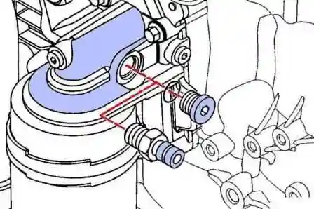
Start the engine and check for oil leaks.
Check the oil level.
Note: maximum oil temperature is 133˚ C.
Removing and installing the oil pan
Disconnect the cable from the negative battery terminal.
Drain the coolant.
Drain the oil from the lubrication system.
Remove the accessory drive belt drive attachments Cummins ISF3.8)
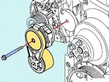
Remove the bolt and remove the accessory wire belt tensioner.
Remove the six mounting bolts and remove the crankshaft speed sensor rotor.
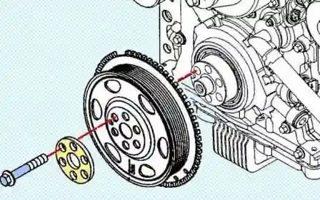
Remove the four mounting bolts and remove the fan and fan pulley
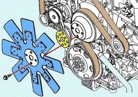
Loosen the clamp and remove the crankcase ventilation hose (if using an open crankcase ventilation system).
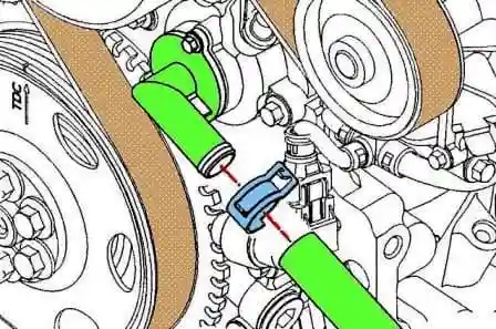
Loosen the clamps and disconnect the intake and exhaust vent hoses (if using a closed crankcase ventilation system).
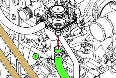
Remove the inlet hose
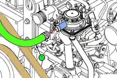
Remove the outlet hose
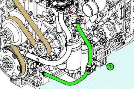
Loosen the clamp and disconnect the drain hose (if using a closed crankcase ventilation system).
Remove the two bolts and remove the camshaft cover
Remove the front crankshaft oil seal.
Disconnect the connector, remove the bolt and remove the camshaft position sensor.
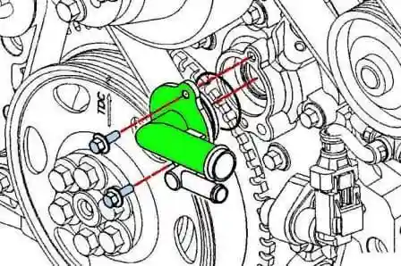
Disconnect the connector, remove the bolt and remove the crankshaft position sensor
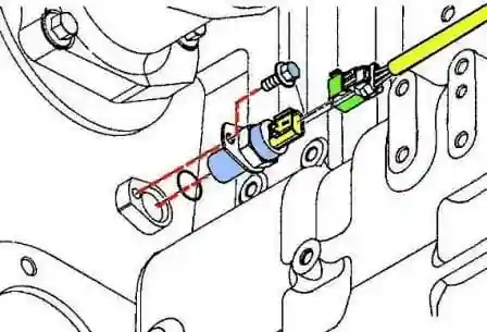
Remove the dipstick guide.
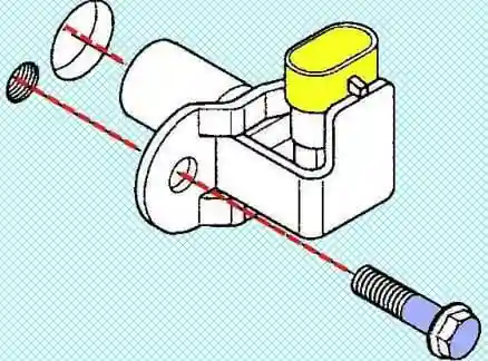
Clean the area around the dipstick guide.
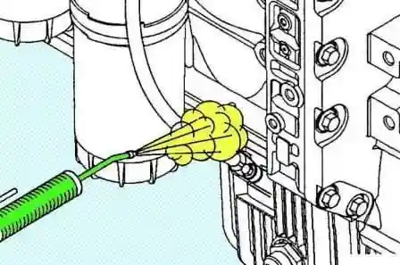
Remove the dipstick, unscrew the mounting bolts and remove the dipstick guide.
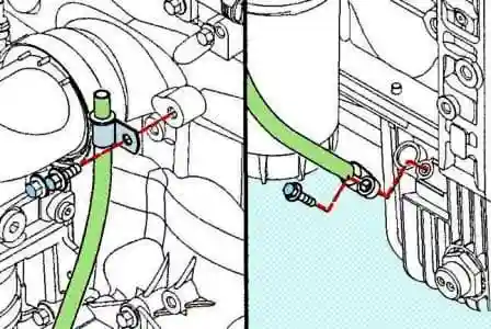
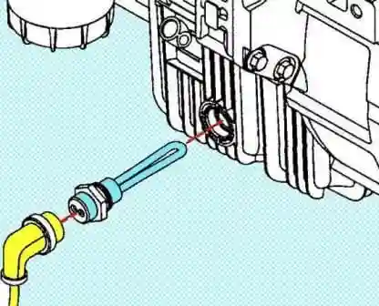
Disconnect the connector and remove the oil heater
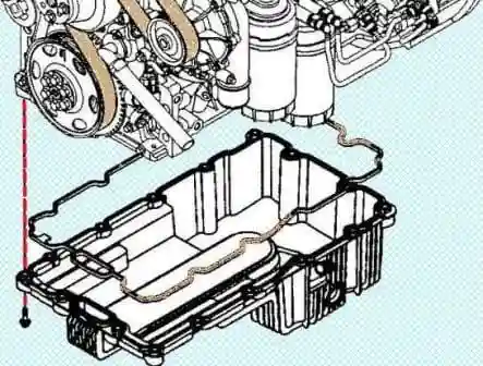
Remove the mounting bolts and remove the oil pan and gasket
Remove the front timing gear cover.
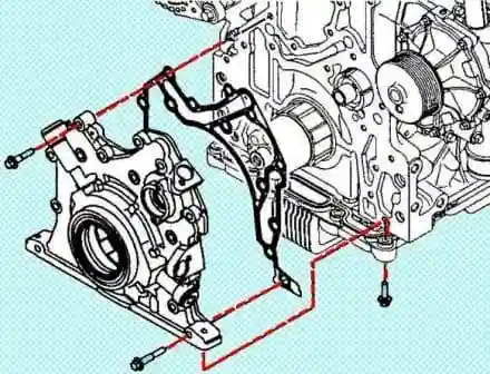
Remove the 14 mounting bolts and remove the front timing gear cover.
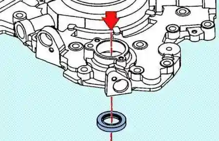
Using a wooden spacer and a hammer, knock out the camshaft oil seal.
Install the front timing gear cover.
Clean the cylinder block of the old seal.
Lubricate the area on the cover of the front camshaft gears under the camshaft oil seal.
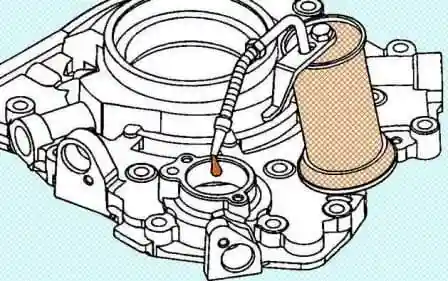
Install the oil seal into the front gear cover using a drift, tapping the drift with a hammer at points 90 degrees apart.
Approximate installation depth of gland 12 mm
Lubricate the camshaft nose with engine oil
Note: Be careful not to damage the rubber seal when installing.
Lubricate the seal with adhesive sealant before installing the cover.
Sealant 3164070 or equivalent
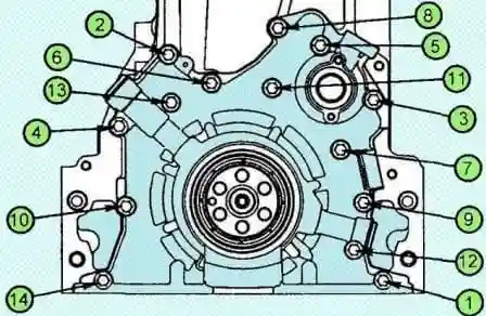
Install the front timing gear cover and tighten the 14 bolts in the order shown in the illustration. Tightening torque 24 Nm
Install the oil pan.
Install a new gasket on the oil pan.
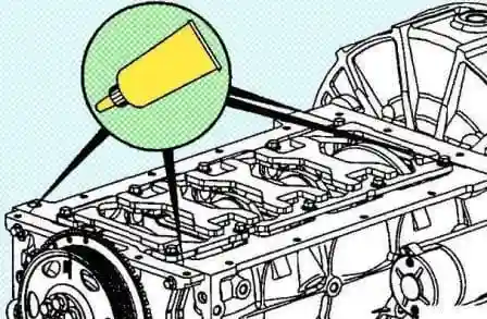
Apply a thin layer of sealant to the areas shown.
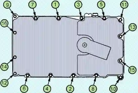
Install the oil pan and tighten the 16 bolts in the sequence shown in the figure. Tightening torque 24 Nm
Install the oil heater and connect the connector. Tightening torque 24 Nm
Install the dipstick guide and tighten the bolts mounts. Tightening torque 5 Nm
Install and tighten the drain plug. Tightening torque 24 Nm
Install the crankshaft position sensor.
Install a new O-ring on the sensor, lubricated with engine oil.
Install the camshaft position sensor and tighten the mounting bolt. Tightening torque 25 Nm
Connect the connector.
Install the camshaft position sensor.
Install a new O-ring on the sensor, lubricated with engine oil.
Install the camshaft position sensor and tighten the mounting bolt. Tightening torque 10 Nm
Connect the connector.
Install the front crankshaft oil seal crankshaft oil seal Cummins ISF3.8)
Install the camshaft cover.
Install a new O-ring and lubricate with sealant.
Sealant 3164070 or equivalent
Install the camshaft trim and tighten the 2 mounting bolts. Tightening torque 7.5 Nm
Connect the drain hose and tighten the clamp (if using a closed crankcase ventilation system). Tightening torque 7.5 Nm
Install the inlet and outlet vent hoses and tighten the clamps (if using a closed crankcase ventilation system). Tightening torque 7.5 Nm
Install the oil pan vent hose and tighten the clamp (if using an open crankcase ventilation system).
Install the fan pulley, fan and tighten the mounting bolts. Torque:
- - M6 - 10 Nm;
- - M10 - 43 Nm;
- - M12 - 77 Nm.
Install the new crankshaft speed sensor and tighten the six criss-cross mounting bolts. Tightening torque 55 Nm
Install the accessory wire belt tensioner and tighten the bolt. Tightening torque 43 Nm
Install the accessory drive belt drive attachments Cummins ISF3.8).
Fill oil into the lubrication system.
Refill coolant.
Connect the cable to the negative battery terminal.
Start the engine and check for leaks.
Disassembly and assembly of the oil pump
Lay the front timing gear cover on a flat surface, front end down.
Remove the 8 oil pump cover bolts and remove the cover.
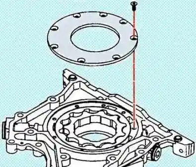
Remove the male and female rotors.
Install the driven rotor, chamfered towards the front timing gear cover.
Install the main rotor by aligning the tab on the rotor with the tab on the front timing gear cover.
If both rotors fit snugly against a common plane, then the rotors are installed correctly.
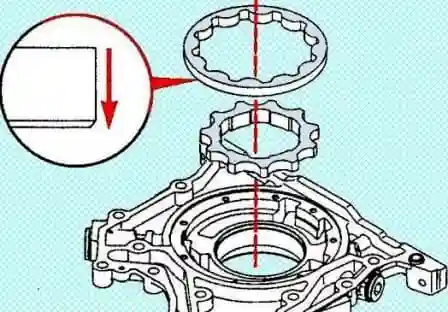
Install the oil pump cover, apply adhesive sealant to the bolt threads and tighten the 8 mounting bolts.
Loctite243 sealant or equivalent
Tightening torque 8.5 Nm
Cleanup and checks
Check the front timing gear cover.
Remove the oil with a solvent and dry the crankshaft pulley with compressed air.
Check for damage and cracks.
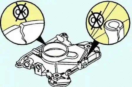
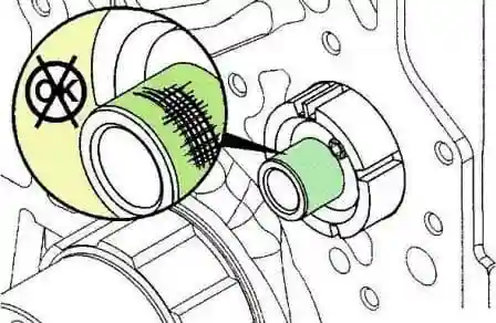
Check the location of the crankshaft front oil seal.
Use solvent to remove oil and sealant residue from the surface of the crankshaft. Dry with compressed air.
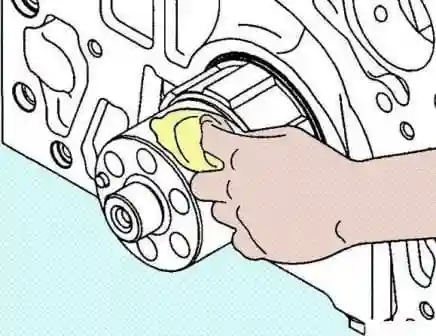
Check for damage to the crankshaft toe and remove minor damage with fine sandpaper.
If the contact surface of the crankshaft nose is damaged, it is impossible to install a repair sleeve on it.
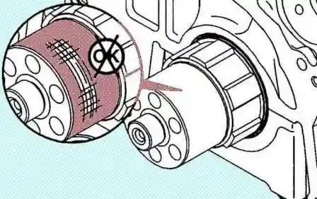
Check the installation location of the front camshaft oil seal.
Use solvent to remove oil and sealant residue from the surface of the camshaft. Dry with compressed air.
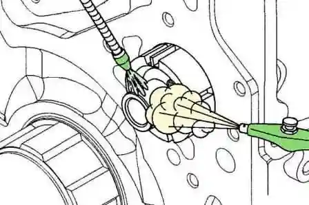
Inspect the camshaft nose for damage and remove minor damage with fine sandpaper.
If the contact surface of the camshaft nose is damaged, it is impossible to install a repair sleeve on it.
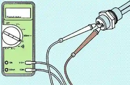
Check the oil heater.
Clean the heating element with a dry towel.
Check for damage to the heating element.
Check the resistance of the heating element. Rated resistance 91 - 101 Ohm
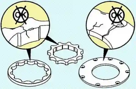
Check the oil pump.
Clean the oil pump with solvent and dry with compressed air.
Check for damage to the rotors and lid.
If damaged, replace the front timing gear cover.
Removing and installing the oil cooler
Drain the coolant.
Remove the accessory drive belt drive attachments Cummins ISF3.8).
Disconnect the radiator hose from the coolant pump.
Disconnect the coolant bypass line.
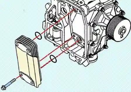
Remove the oil cooler.
Remove the mounting bolts, remove the coolant pump housing with oil cooler and seal.
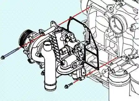
Remove the four mounting bolts and remove the oil cooler
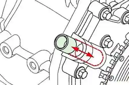
Remove the pressure reducing valve of the lubrication system.
Remove any dirt around the pressure reducing valve spring seat
Remove the relief valve by removing the spring seat, O-ring, spring and plug.
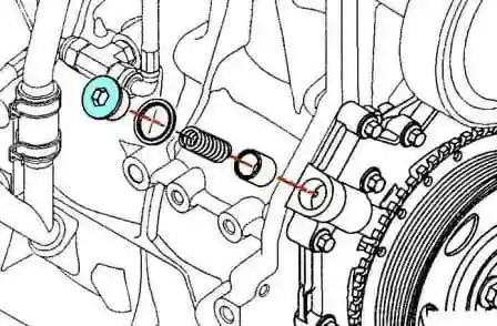
Install the pressure reducing valve.
Install a new O-ring on the spring seat and lubricate the parts with engine oil.
Install the relief valve by installing the plunger, spring and spring seat. Tightening torque 80 Nm
Install the oil cooler.
Install the oil cooler and tighten the 4 bolts. Tightening torque 15 Nm
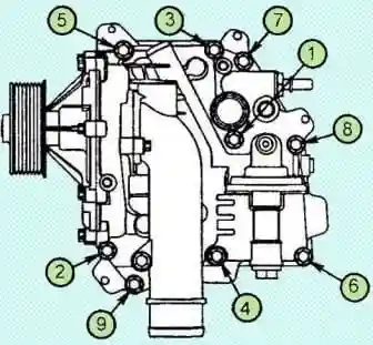
Install the water pump housing, gasket, and tighten the mounting bolts in the order shown in the figure. Tightening torque 27 Nm
Connect the cooling system bypass line.
Connect the radiator hose to the coolant pump.
Install the accessory drive belt.
Refill coolant.
Start the engine and make sure there are no See leaks.
Cleanup and checks
Check the pressure reducing valve.
Solvent clean the plunger, spring and spring seat and dry the parts with compressed air.
Note: If you need to clean the plug hole, remove the body.
Check for damage to the plunger.
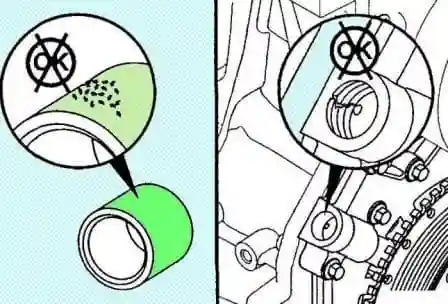
Make sure the plunger moves freely in the pressure reducing valve body
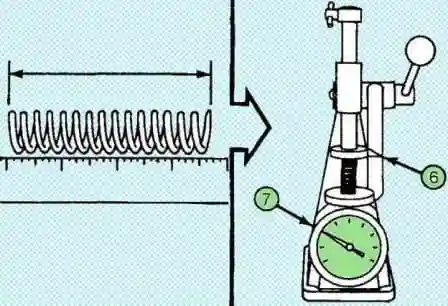
With a valve spring tester, measure the spring force of the pressure reducing valve at the following heights:
Reducing valve spring force
|
Height |
Effort |
|---|---|
|
42.6 mm |
155 – 165 Nm |
|
30.7 mm |
311 – 339 Nm |
Check the oil cooler.
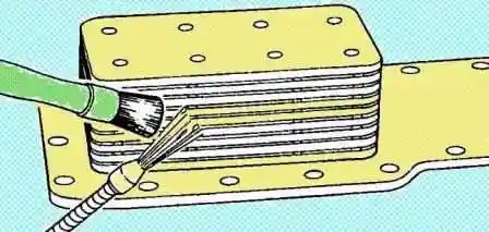
Use a solvent to clean the housing and oil cooler cover and dry with compressed air.
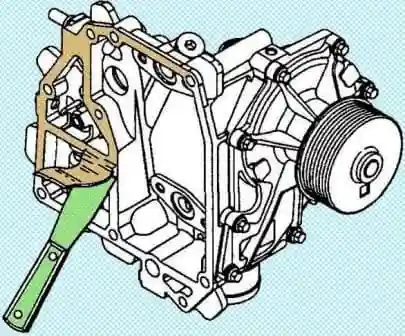
Clean seal surfaces.
Check the oil cooler for leaks using a pressure test kit.
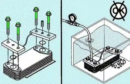
Oil cooler pressure test kit #4918868
Air pressing:
- - minimum pressure 449 kPa
- - maximum pressure 518 kPa.


