
The exhaust gas treatment system is designed to reduce emissions of nitrogen oxides from the engine.
Exhaust system resistance measurement
Connect a pressure gauge to the outlet pressure port.
Install the pressure gauge no more than one pipe diameter from the turbocharger outlet.
Let the engine run at minimum speed and load.
Measure the backpressure in the exhaust system.
Maximum exhaust system resistance 40 kPa

If the pressure in the exhaust system is higher than the maximum, check it for damage.

Remove the pressure gauge. Replace the plug if necessary.

Removing and installing exhaust manifold
Disconnect the wires from the battery terminals.
Remove the turbocharger inlet and outlet pipes.
Disconnect the charge air cooler air pipes.
Remove the turbocharger Cummins ISF3.8
Remove the exhaust manifold.
Remove the exhaust manifold mounting bolts.
Remove the spacers, exhaust manifold and gaskets.

Check
Clean the exhaust manifold.
Clean the exhaust manifold with steam. Dry with compressed air.
Use #240 sandpaper to remove carbon deposits from the contact surfaces.

Use a precision straightedge to check the flatness of the exhaust manifold bearing surfaces.

Place a straight edge over all holes and measure the flatness with a feeler gauge. Maximum flatness 0.2 mm
If flatness is greater than maximum, grind or replace exhaust manifold.
Installation
Install the exhaust manifold.
Apply high temperature anti-seize compound to the threads of the exhaust manifold mounting bolts.
Install new gaskets, exhaust manifold, spacers and retaining plates, tighten the bolts.
Tighten the exhaust manifold mounting bolts in the sequence shown in the illustration. Tightening torque 53 Nm

Install the turbocharger (article Removing the components of the Cummins air intake system ISF3.8).
Install the charge air cooler air pipes.
Install the turbocharger inlet and outlet.
Connect the wires to the battery terminals.
Start the engine and check for leaks.
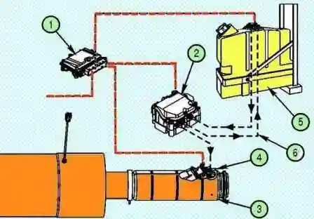
Selective Catalytic Converter Emission Control System
Caution: after stopping the engine, wait until the emission control fluid dispenser has completely purged the system.
To do this, turn off the ignition and wait until the selective cataleptic converter has cooled down.
The dispenser makes an audible pumping noise, similar to the sound of a booster pump, for five minutes after the ignition is turned off.
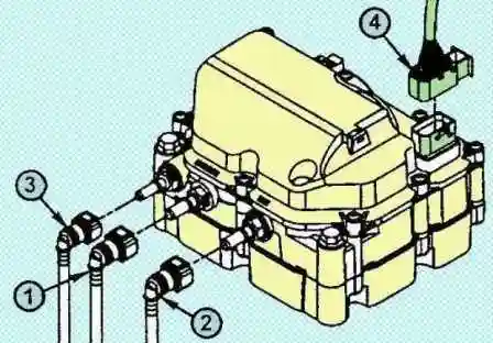
Emission control fluid dispenser
The dispenser draws the emission control fluid from the reservoir and delivers it to the dispenser valve. All unused liquid is fed back into the reservoir.
The dispenser is powered by 12 V or 24 V.
The nominal voltage value is stamped on the dispenser housing, next to the electrical connector.
In addition, the dispenser differs in its connector.
If the face of the electrical connector on the harness side is grey, then the dispenser is running on 24VDC.
If the surface is black, the dispenser is powered by 12 VDC.
Electrical connectors have different latches, which excludes their interchangeability.

Initial check
Check the inlet and outlet fittings of the dispenser for leaks (white coating around the damaged fitting).

If deposits are found, check the fittings for cracks.

Check the area around the dispenser cap for leaks.
Withdrawal
- The pipeline connecting the dispenser to the valve is under low pressure and must not be disconnected while the engine is running or until the system has been cleaned after the engine has stopped.
Disconnecting this line may cause emission control fluid to leak.
- Do not disconnect batteries until the dispenser purge cycle is complete.
Wait at least 5 minutes after turning off the ignition before removing and/or disconnecting any components or parts from the dispenser in preparation for purging.
The purge cycle is automatic and requires no intervention.
During the purge of the dispenser, a characteristic sound of the pump is heard.
- Do not wash the dispenser with water or steam. Use compressed air for cleaning.
Disconnect the cable from the negative battery terminal. Then from positive.
Tag all emission control lines and their connectors.
If the piping is connected incorrectly, the system will not function and the fault indicator will light up.
Disconnect the emission control lines and electrical connector in the order shown to reduce the possibility of contamination of the electrical connector with emission control fluid.
Slide the connector towards the yellow part. After the connector begins to rise, disconnect it from the dispenser.
Cover the fittings and connector to prevent dirt from entering.
Remove the three bolts and remove the dispenser.

Note: The dispenser is only disassembled if there are signs of a malfunction that require it to be opened.
Unscrew the dispenser fittings.

Make sure the o-rings are on the fittings and not stuck inside the dispenser.
Cleanup and validation
The dispenser is not serviceable. Do not open its case. Return the unit to a Cummins Authorized Service Center.
- - Do not immerse the block in any cleaning solution.
- - Do not use any detergent to wash the block.
- - use a clean damp cloth to wipe the block.
Visually inspect the dispenser. If you find any cracks, damage to the housing or electrical connectors, replace it.
If the dispenser filter cap is damaged, replace it.
Check the emission control system fluid line connections for damage or signs of corrosion.
Note: If damage or corrosion is found, check the emission control fluid line fittings.

The inlet port (1) and return port (2) of the dispenser have a built-in, maintenance-free strainer.
Using a rubber-tipped air gun, blow the connectors onto a piece of white paper in the opposite direction of the fluid flow.
Check for debris on the paper as a result of blowing. Debris particles indicate a clogged connector.
If the connector is clogged, it should be replaced.

If contamination is found in the inlet fitting of the emission control system metering valve, check the emission control system fluid reservoir filter.
Installation
Note: dispenser fittings are not interchangeable.
Install the fittings. Do not apply grease or sealant. Tightening torque 4 Nm
Note: Before installing the dispenser on a vehicle, make sure it is free of contaminants.
To reduce false reports of emission control fluid leaks, use a clean, damp cloth to wipe up any spilled fluid during repairs.
Place the dispenser on the support bracket and secure it with three bolts. Tightening torque 20 Nm
Note: Do not replace a 12V dispenser with a 24V unit and vice versa.
Connect the electrical connector. Emission control fluid can corrode the electrical connector pins.
The 12-pin electrical connector (4) is installed by pushing the yellow part inwards. The connector will lower and lock onto the dispenser.
Connect the emission control lines in the order shown to reduce the chance of accidental fluid contamination of the electrical connector.
The connectors of the liquid pipelines of the exhaust gas toxicity reduction system make a characteristic click when fixed on the fittings.
Pull lightly on the connector to make sure it is secure.
Connect the wires to the battery terminals.
Make sure there are no trouble codes. Note: To check the emission control fluid supply, warm up the catalytic converter by driving for more than 15 minutes.
Emission control fluid filter
Removal and installation
Check the area around the filter cap for leaks (white coating around the leak).

Remove the wires from the battery terminals.
Clean the dispenser with a clean damp cloth.
Note: Do not flush the dispenser with water or pressurized steam.
Remove the filter cover.
Unscrew the cover (1) of the liquid filter of the systems reducing the toxicity of exhaust gases.
Remove the cover and O-ring (2). c)
Pull out the filter element (3) of the emission control fluid.

Clean the cover and make sure it is not damaged.
Install the new filter element in the reverse order of removal. Tightening torque 20 Nm
Connect the wires to the battery terminals.
Start the engine and check for leaks.
Emission control fluid dosing valve
The emission control fluid dosing valve is used to inject fluid into the exhaust stream before the catalyst inlet.
The emission control fluid dosing valve is located on the decomposition tube, which is fixed to the flange with three bolts.
The emission control fluid dosing valve has three main connectors:
- - 2-pin electrical connector that connects the emission control fluid dosing valve to the control unit.
- - The emission control fluid supply line that connects the metering valve to the metering device.
- - The coolant supply/drain fitting that connects the emission control fluid metering valve to the engine cooling system.

Initial check
Note: Emissions control fluid deposits may be left over from previously spilled fluid or from repairs.
Before replacing any components and parts, check the system for leaks.
Check the area around the junction of the emission control fluid supply line to the metering valve.
Check for leaks and/or white deposits in the following areas:
Connection between emission control fluid supply line and metering valve.
Connections between the emission control fluid dosing valve and its housing.
Deposits can hide a leak, so remove the deposits and rinse with warm water.

Withdrawal
Disconnect the wires from the battery terminals.
Drain the coolant.
Remove any dirt from the quick coupling and around the dosing valve body.
Remove the coolant hoses next to the emission control fluid hoses and disconnect the electrical connector from the metering valve.

Close the fittings with plugs.
Remove the metering valve gasket.
Remove the screws securing the dosing valve to the digestion tube.
Check
Check the condition of the dosing valve.
If leaks/deposits are found at the Emission Control Fluid dosing valve connections between the valve and its body during checks, replace the dosing valve.
If leaks/deposits are found at the Emission Control Fluid Line Connector during checks, check the connector for cracks or corrosion.
Check the electrical connector and its contacts for damage/corrosion.
Note: If damage or signs of corrosion are found, also inspect the Emissions Control fluid line connector.
If damage is found, replace the emission control fluid dosing valve.
Note: Do not disassemble the emission control fluid dosing valve. This part is not serviceable.

Check the fluid flow of the emission control system.
Caution: Do not stand near the Emission System Fluid Test Tank, especially in a room with poor air circulation, as breathing may be affected.
The purpose of this test is to activate the emission control fluid dispenser and ensure that the target amount of the emission control fluid solution is delivered within the specified amount of time.
The test is launched using the INSITE diagnostic complex. The test is performed automatically.
The test is carried out under the following conditions: the car is stationary, the gear is in neutral, the key is in the “ON” position.
During operation, 3 cycles take place: pumping, feeding and cleaning. Install the valve in a container with a volume of more than 4 liters.
Cover the valve with a cloth or oilcloth to prevent splashing.
The check lasts 5 minutes. After checking, measure the amount of liquid.
Liquid volume 106 - 144 ml

If the liquid value does not correspond to the nominal value:
- - Check the filling of the emission control fluid dispenser.
- - Make sure the system lines are not clogged or narrowed.
- - Check the emission control filter.
- - Check again. If the flow rate is different from the nominal, replace the dispenser.
Installation
Make sure the battery is disconnected.
Install the metering valve with a new gasket and tighten the mounting screws. Tightening torque 8 Nm
Connect the quick connectors.
Connect the electrical connector.
Remove plugs and connect lines.
Refill coolant.
Connect the wires to the battery terminals.
Start the engine and check for leaks.
Check for diagnostic trouble codes.
Checking Consumption
Perform a dispensing cycle and check the following characteristics:
- - the shape and spray pattern of the liquid dosing valve of the exhaust gas toxicity reduction system;
- - the amount of liquid of the exhaust gas toxicity reduction system supplied for a certain time (6 minutes).
This test can be performed using the INSITE diagnostic tool when diagnosing the ECM. Follow the instructions on the display to complete the test.
Note: Low battery voltage may result in reduced fluid volume. Check batteries before testing.
Disconnect the wires from the battery terminals.
Remove the emission control fluid dosing valve.
Caution: Do not connect 12V or 24V DC to the emission control fluid dosing valve to avoid damaging it.
Connect the electrical connector and the emission control fluid lines.
Note: This test does not require a coolant circuit connection.
Use a clear plastic container large enough to hold the emission control fluid dosing valve and measuring cup (500 ml, 5 ml increments).

Place the emission control fluid dosing valve in a container.
Note: The test starts with filling the dosing system.
During this process, the emission control fluid metering valve is periodically opened to bleed air from the system.
This may cause some of the emission control fluid to splash out, which is not a malfunction.
When checking, the emission control fluid dosing valve sprays the fluid in the form of very fine droplets.
To prevent small liquid droplets from escaping and to ensure measurement accuracy, place a clean bag or cap over the valve and container.

At the start of the test, slightly adjust the spray pattern of the fluid emitted by the emission control fluid dosing valve.
Please note the following:
- - the appearance of too large drops and dripping of liquid from the tip;
- - violation of the symmetry of the spray shape (shifting it in any direction).
If any of these symptoms are found, stop testing and check the tip of the emission control fluid metering valve.
If necessary, recheck and adjust the spray pattern.
If the problem persists, replace the emission control fluid dosing valve.

Check fluid flow.
- - Turn on the ignition.
- - Connect the INSITE diagnostic complex.
- - Select the item in the ECM diagnostic test menu related to the test with forced turn on of the pump by the emission control fluid proportioner.
- - follow the instructions on the display to perform the test.
The INSITE diagnostic system will run a test, during which the liquid will be injected for 6 minutes.
At the end of the test, the INSITE diagnostic complex will automatically stop spraying.
If you need to stop the test before it is complete, click the “STOP” button.

After completing the check, measure the amount of emission control fluid injected into the container.
Pour the emission control fluid into a measuring container.
Perform the check three times and average the results of the checks.
Minimum volume 85 ml
Maximum volume 115 ml
Note: Do not drain the emission control fluid back into the tank.
Dispose of it in accordance with local environmental regulations.

If the amount of emission control fluid is not correct, check that the fluid filter is not clogged.
Check the piping between the proportioner and the emission control fluid dosing valve for leaks, blockages, or excessive resistance.
Note: The emission control fluid dosing valve may be clogged with debris.
Inspect the emission control fluid metering filter for signs of contamination or blockage before installing a new emission control fluid metering valve.
Using a clean tech cloth dipped in warm water, remove the layer of emission control fluid from the equipment before disconnecting it.
Install the dosing valve.
Air in Emission Control Fluid
Disconnect the metering valve diesel emission control supply line.
Install the optional emission control fluid line (P/N 4919574).
Install a container suitable for collecting the emission control system fluid at the outlet of the emission control system supply line.
We recommend using a 3.8L pail.

Lower the end of the outlet hose from the secondary emission control fluid line into a container to collect the fluid.
Turn on the ignition and connect the INSITE diagnostic complex
Select the item in the ECU diagnostic test menu related to checking the manual operation of the emission control metering pump.
This test attempts to fill the dosing system.
At the same time, the emission control system fluid is drained from the tank and pumped through the additional emission control fluid supply line.
Note: If the test has started, the pump will continue to supply Emission Control Fluid even after an attempt to stop the test using the INSITE diagnostic tool. To stop the test, turn off the ignition.
While performing a manual pump test, observe fluid flow from the secondary emission control fluid line.
The appearance of bubbles indicates a leak allowing air to enter the dosing system.
If there are bubbles, check the following parts for damage or leaks:
- - fittings of the dispenser of the system for reducing the toxicity of exhaust gases of diesel engines;
- - the supply pipeline of the dispenser of the exhaust gas toxicity reduction system;
- - fluid reservoir for the exhaust gas emission reduction system;
- - fittings of the reservoir with liquid of the exhaust gas toxicity reduction system.
Repair or replace damaged parts.

Turn off the ignition to complete the test.

Note: If this test continues too long, DTC 1682 becomes active. The duration of the check should not exceed 5 minutes.

")
")
")
")
")
")
")
")