


Dismantling the engine for a major overhaul.
As a rule, a major overhaul of the engine is required at high mileage, when the oil pressure drops and when the compression in the engine cylinders drops.
We remove the engine attachments, the removal of which is covered in separate articles.
We remove the alternator, the starter motor, the cylinder head, the water pump and the upper clutch housing cover.
Removal of the oil sump and oil pick-up
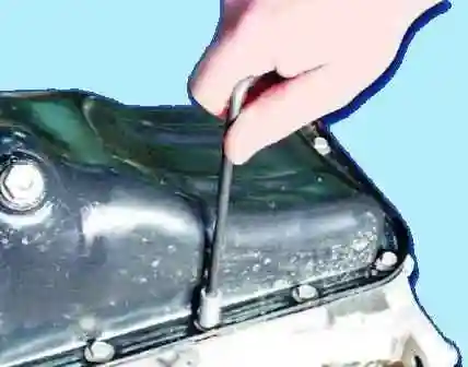
- Using a 10 mm spanner or socket, we unscrew the sixteen bolts securing the sump.
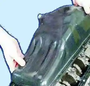
- We remove the oil sump together with the gasket.
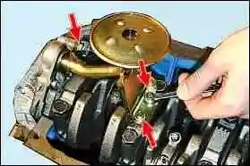
- We unscrew the two bolts securing the oil pick-up to the crankshaft support cover.
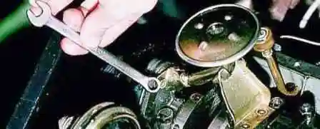
- We unscrew the mounting bolt to the oil pump.
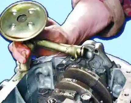
- We withdraw the pick-up tube from the oil pump and remove the oil pick-up.
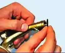
Note: if the sealing ring is damaged, it must be replaced.
Removal of the oil pump
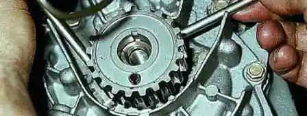
- With two screwdrivers we prise off the toothed pulley.
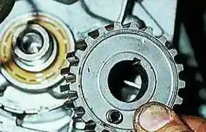
- We remove the toothed pulley from the crankshaft nose.
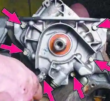
- We unscrew the six bolts securing the oil pump.
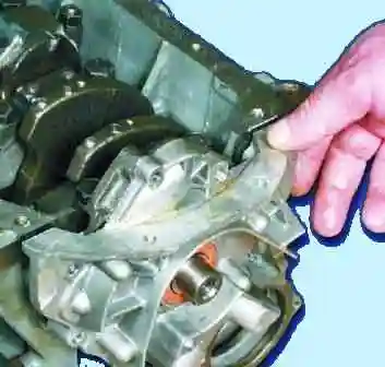
- We remove the oil pump.
Removal of the right-hand engine mounting
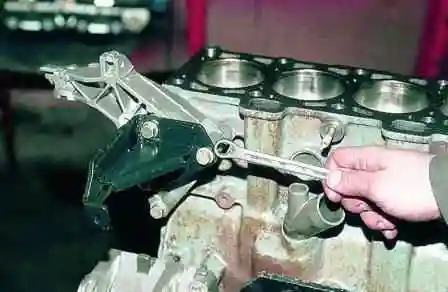
Using a ring spanner or a 13 mm socket, we unscrew the two bolts securing the alternator bracket and the right-hand engine mounting bracket.
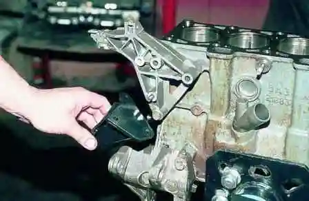
We remove the alternator mounting bracket.
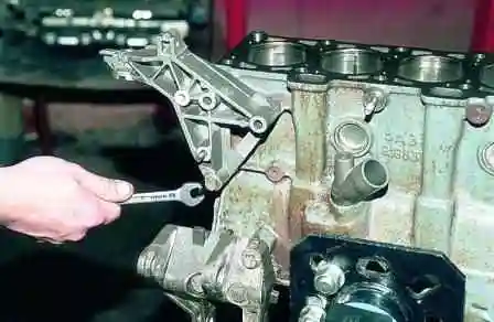
We unscrew the lower bolt of the right-hand mounting.
Using a 15 mm socket, we unscrew the three bolts securing the alternator bracket.
We remove the right-hand mounting bracket.
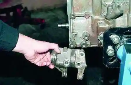
We remove the alternator bracket.
Removal of the coolant pump inlet pipe
Using a 10 mm spanner or socket, we unscrew the two bolts securing the coolant pump inlet pipe.
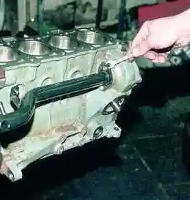
We remove the pipe and gasket.
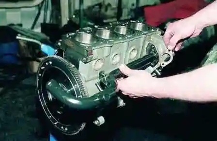
Removal of the crankshaft rear seal retainer
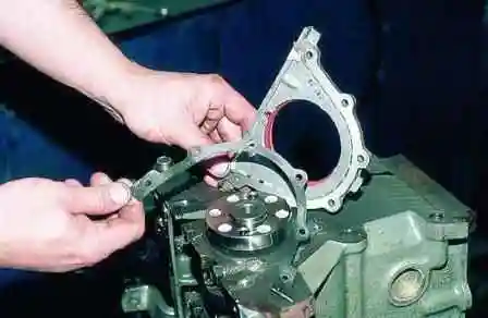
Using a 10 mm spanner or socket, we unscrew the six bolts securing the crankshaft rear seal retainer.
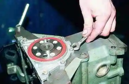
We remove the retainer and gasket.
Dismantling the connecting rod and piston assembly
Using a 14 mm socket, we unscrew the connecting rod cap mounting nuts.
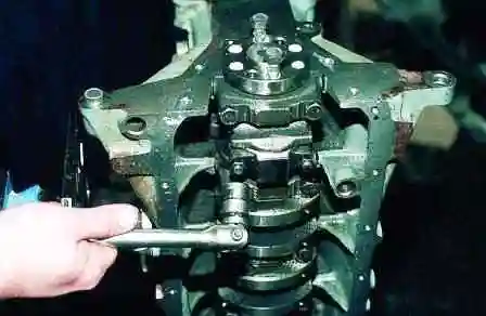
We remove the connecting rod cap.
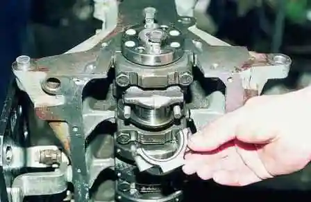
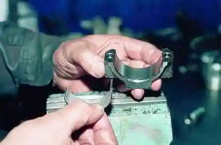
We extract the bearing shell from the cap.
- Resting the wooden handle of a hammer against the connecting rod, we push the piston out.
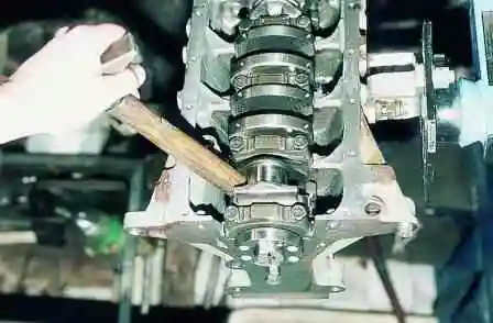
From the other side we extract the piston with rings from the cylinder.
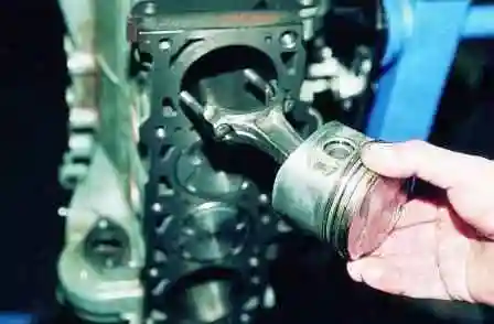
In the same way we extract the remaining three pistons.
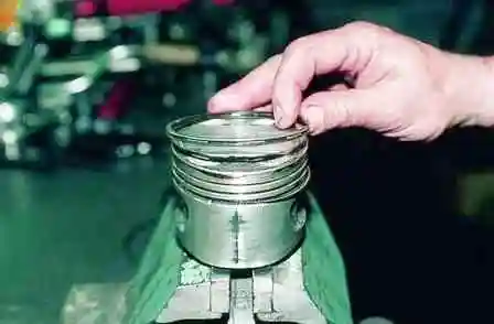
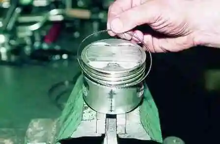
Removal of the piston rings
Using special pliers, we spread and remove the rings from the pistons. If pliers are not available, we carefully spread the ring gaps with our fingers and remove the compression rings one by one.
We also remove the oil scraper ring.
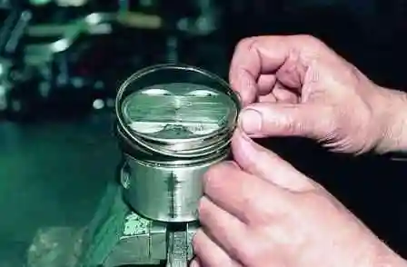
We remove the ring expander. If the oil scraper ring is of the disc type, we remove the discs and the expander.
Removal of the piston pin
With a screwdriver we prise off the piston pin circlip and extract it from the annular groove of the piston.
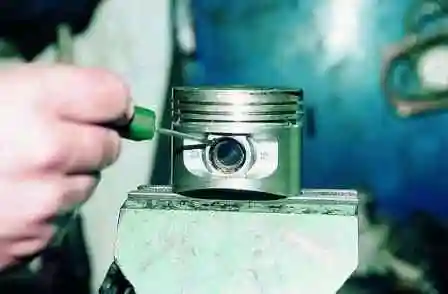
We also extract the second circlip.
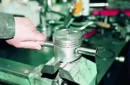
With a drift we drive out the piston pin and separate the piston from the connecting rod.
Removal of the crankshaft
Using a 17 mm socket, we unscrew the ten bolts securing the crankshaft main bearing caps.
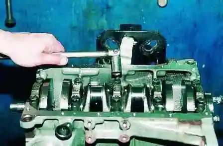
We extract the caps.
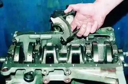
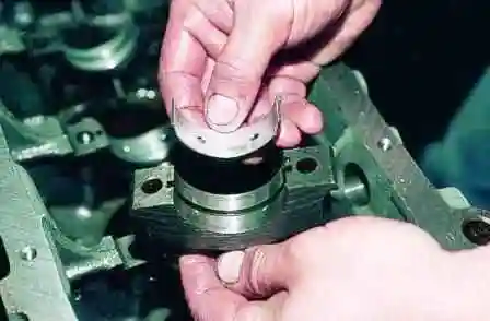
We extract the bearing shells from the caps.
We extract the crankshaft.
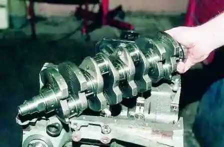
Important! We lay the engine parts out in order on racks and mark them so that everything is refitted in its place during assembly.
We extract the thrust half-rings from the grooves of the centre main bearing support.
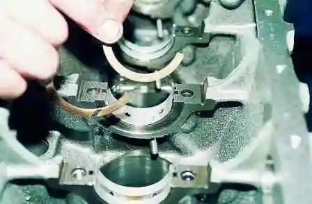
We extract the main bearing shells from the cylinder block seats.
Jets for cooling the pistons are pressed into the main bearing seats of the block.
Note: if the connecting rod and piston assembly parts are undamaged and only slightly worn, they can be reused. Therefore, when dismantling, the parts must be marked so that they are refitted in their places during subsequent assembly.


