


We carry out the inspection and repair of the block during a major engine overhaul.
All cylinder block measurements must be taken when the block is on a flat horizontal surface and all main bearing caps are installed.
Check the cylinder surface for hone marks.
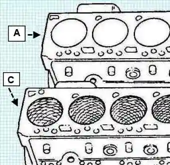
Cross-hatched lines inclined at 20–25° to the top face of the cylinder block must be visible on the cylinder surface.
If necessary, hone the cylinders.
Check the main bearing bores.
- Install the main bearing caps without shells.
- Tighten the main bearing bolts. Tightening torque: 176 N·m.
Measure the main bearing bore diameter. Main bearing bore diameter: 87.983–88.019 mm.
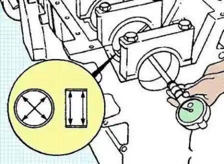
Note: if the main bearing bore diameters do not correspond to the nominal values, check the correct installation and orientation of the main bearing caps. If the main bearing caps are installed correctly, replace the cylinder block.
Check the flatness of the cylinder block using a precision straight edge and a feeler gauge.
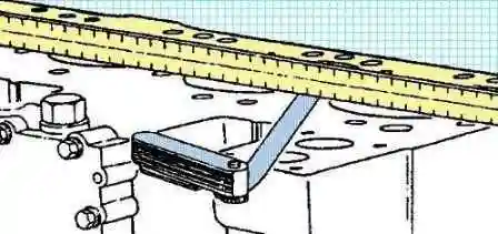
Maximum flatness deviation:
- longitudinal: 0.076 mm;
- transverse: 0.051 mm.
Check for the absence of small irregularities or defects. If present, the top surface of the cylinder block must be ground.
Note: grinding of the top surface of the cylinder block is permitted only if the required piston protrusion height can subsequently be ensured. After grinding of the top surface of the cylinder block, the use of repair gaskets is provided for. If the required piston protrusion height cannot be ensured after grinding, replace the cylinder block.
Measure the cylinder bore diameter.
Note: during measurement, honing or boring of the cylinders, all main bearing caps must be installed and the bolts tightened to the nominal torque.
Check the cylinder surface for the absence of damage and excessive wear.
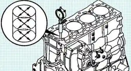
Using a bore gauge, measure the cylinder diameter at 4 points 90° apart at the extreme piston stroke positions. Take the cylinder diameter measurement at a depth of more than 50 mm from the top surface of the cylinder block.
- Cylinder diameter: 102.01–102.03 mm.
- Maximum ovality: 0.038 mm.
- Maximum taper: 0.076 mm.
Check the internal diameter of the camshaft bore with the bush removed.
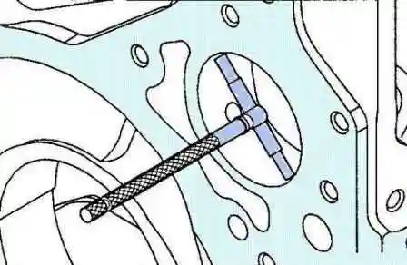
Maximum diameter: 59.248 mm.
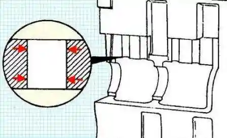
Check the tappet bores for damage and wear. Tappet bore diameter: 16.000–16.055 mm.
Cylinder block repair
Important! The ingress of foreign particles formed during repair operations into the engine oil passages is not permitted. Failure to comply with this requirement will result in engine failure.
After boring or honing in an external repair workshop, it is recommended to wash and blow through the cylinder block without fail.
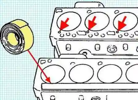
Before repairing the cylinders, be sure to mask the oil passages and tappet holes in the upper part of the cylinder block with water-resistant tape.
Restoring honing of the cylinder liner surface when glazing appears on the walls (if necessary). Honing ensures oil retention on the cylinder walls, which is necessary for the normal operation of the piston rings.
Honing is permitted only if the cylinder dimensions correspond to the nominal values.
Note: the seating of new piston rings in cylinders with a glazed surface will be poor.
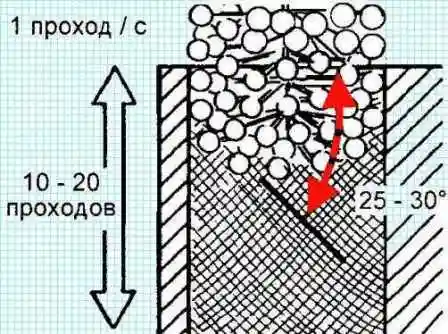
Use a round honing head (No. 3823612 or similar) with a rotational speed of 300–400 rpm, performing one vertical movement cycle per second.
Use high-quality honing oil or a mixture of equal parts SAE30W engine oil and diesel fuel.
Note: the vertical strokes must be smooth and continuous over the entire cylinder height. Check the cylinder bore after 10 strokes.
The angle of the cross-hatched lines depends on the rotational speed and the vertical movement speed of the honing head. Too high or too low a movement speed will cause this angle to deviate from the norm.
On a correctly honed cylinder surface, the hone lines must run at 20–25° to the top face of the cylinder block.
Wash the cylinder block with hot water and detergent concentrate until the abrasive particles are completely removed. Wash the cylinder surface with solvent. Dry the cylinder block with compressed air.
Cylinder liner replacement
The cylinder block must be bored for the installation of repair liners. The use of repair liners allows nominal-size pistons and rings to be used.
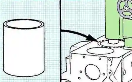
Bore the cylinder to the required size.
- Cylinder bore diameter: 104.500–104.515 mm.
- Maximum cylinder bore depth: 192.65 mm.
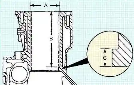
As a result, a step 6.35 mm high must form in the lower part of the cylinder, on which the liner will be seated. Carefully clean the cylinder block of metal chips.
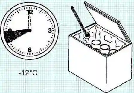
Place the repair liners in a freezer at a temperature below −12 °C for at least 1 hour.
Note: take the liners out one at a time immediately before installation.
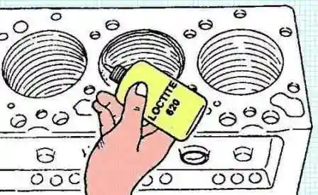
Apply Loctite 620 sealant to the upper part of the cylinder block bore immediately before installing the liner.
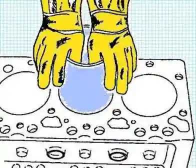
Put on protective gloves and push the cooled liner into the cylinder block by hand as far as possible.
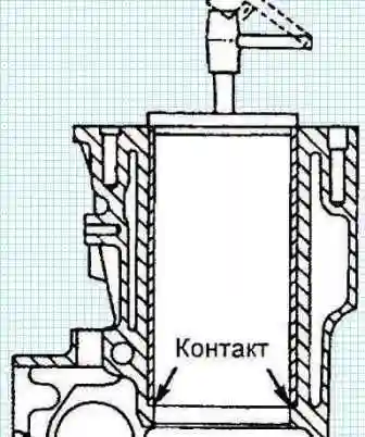
Using a press, press the liner into the cylinder block until it contacts the step in the lower part of the bore.
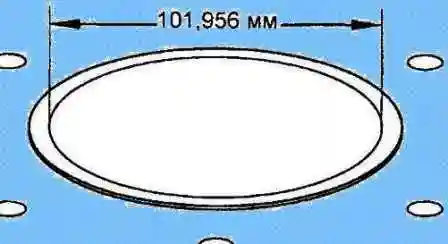
Bore the installed liner to the nominal size. Nominal diameter: 101.956 mm.
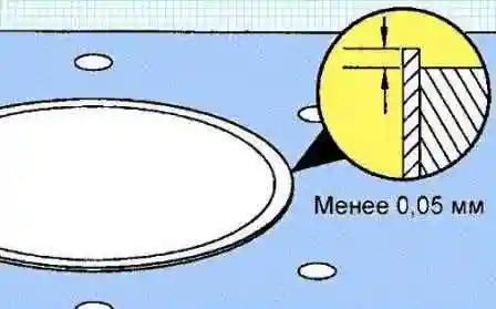
Machine the upper part of the liner so that its protrusion is less than 0.05 mm above the cylinder block surface.
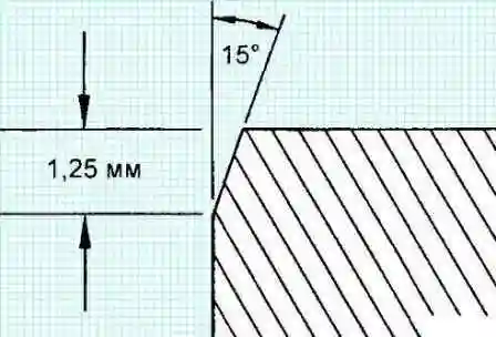
After boring, using a honing stone, make a chamfer 1.25 mm deep at 15° to the vertical.
After boring the repair liner, two-stage honing is necessary to complete the cylinder machining. Use high-quality honing equipment.
During honing, the honing head speed must be 300–400 rpm and the up-and-down stroke time 1 s. Use high-quality honing oil or prepare a mixture of equal parts SAE30W engine oil and diesel fuel.
For the first honing stage, use silicon carbide stones of 80 grit. Hone the cylinders to the final size. Diameter: 102.00–102.04 mm.
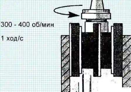
In the second honing stage (finish honing), use silicon carbide stones of 285 grit.
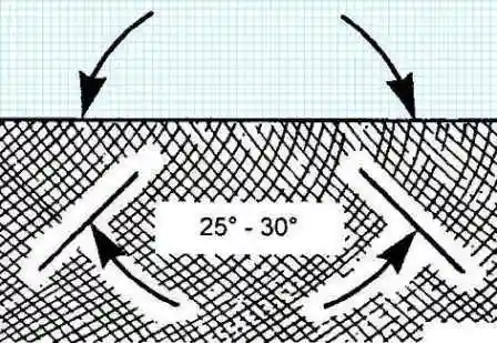
Make 15–20 strokes, giving the hone the required inclination angle.
After finishing the machining, thoroughly wash and blow through all passages to remove chips, dirt, metal particles and oil.


