


Timing belt of the VAZ-2112 engine
The timing belt of the VAZ-2112 engine is reinforced compared with the VAZ-2110 and VAZ-2109 engines. It is wider in size owing to the higher loads.
The belt drives two camshafts (the inlet valve shaft and the exhaust valve shaft) and the coolant pump. The toothed pulleys and rollers are also wide — matched to the belt width. The belt width is 25.4 mm.
For correct installation of the timing belt and for setting top dead centre (TDC), there are marks on the camshaft pulleys and on the rear cover of the camshaft drive. Accordingly, there is also a mark on the crankshaft pulley and on the oil pump.
The design of the VAZ-2112 engine does not prevent a sudden belt failure; however, if the belt breaks, the pistons may strike the valves. Therefore, the condition of the belt must be carefully inspected during periodic maintenance. For ease of inspection, an access hatch is provided in the upper timing belt cover.
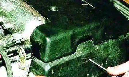
- To inspect the condition of the belt, prise off the hatch with a screwdriver.
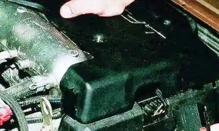
- We inspect the condition of the belt; it is best to turn the crankshaft so as to inspect the entire belt.
On later modifications of the VAZ-21124 and VAZ-21126 engines, recesses are already provided in the pistons, which protect the pistons and valves from impact.
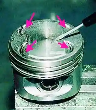
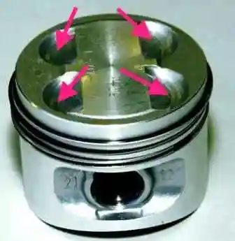
Replacing the timing belt
To replace the timing belt, the alternator drive belt must first be removed.
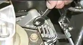
- Using a 13 mm spanner, loosen the nut securing the alternator to the tensioning bracket.
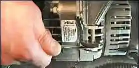
- Using a 10 mm spanner, unscrew the adjusting bolt and slacken the belt. Remove it from the crankshaft and alternator pulleys.
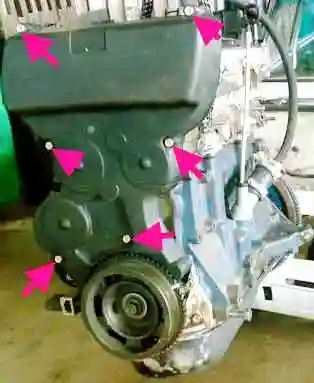
- Using a 10 mm socket, unscrew the six bolts securing the front cover.
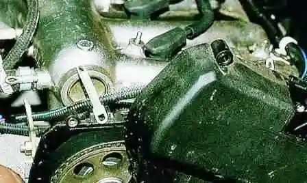
- Remove the timing belt cover.
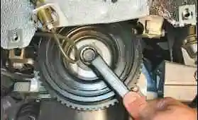
- Using a 17 mm spanner, turn the crankshaft clockwise by the bolt securing the alternator drive pulley.
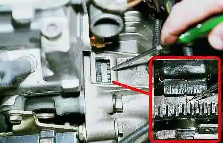
- Turn until the mark on the flywheel coincides with that on the clutch housing cover.
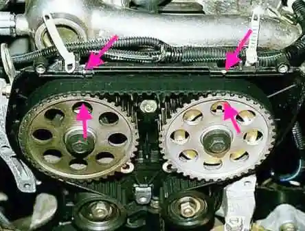
- The marks on the camshaft toothed pulleys must then coincide with the marks on the rear timing belt cover.
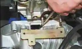
- To unscrew the bolt securing the alternator drive pulley, lock the flywheel with a screwdriver to prevent it from turning.
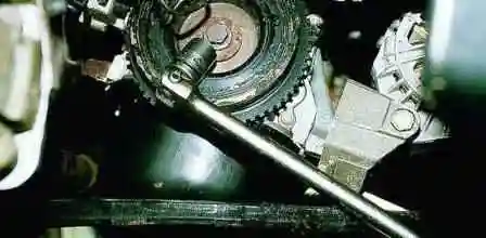
- Using a 17 mm socket or a box spanner, unscrew the pulley securing bolt.
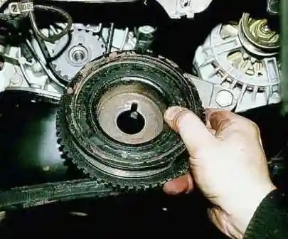
- Remove the alternator drive pulley.
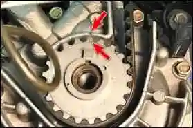
- On the crankshaft toothed pulley, when setting TDC, the mark must coincide with the slot on the oil pump.
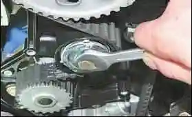
- Using a 17 mm spanner, loosen the timing belt tensioner pulley nut.
- By turning the pulley, slacken the belt tension and remove its rear run from the exhaust camshaft toothed pulley, the tensioner pulley and the coolant pump pulley.
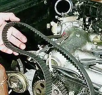
- Remove the belt from the crankshaft and exhaust camshaft toothed pulleys and from the support roller.
Installing the timing belt
- Install the belt in the reverse order.
- Make sure that the setting marks of the crankshaft and camshafts coincide.
- Fit the toothed belt onto the crankshaft pulley.
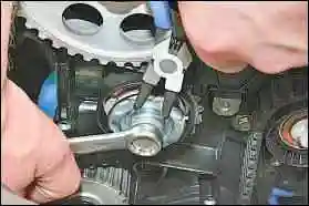
- By turning the tensioner pulley, tension the belt and secure the pulley.
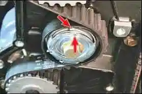
- When tensioning the belt, the cut-out on the outer disc must coincide with the projection on the inner sleeve of the tensioner pulley.
- After turning the crankshaft two revolutions in the direction of rotation, check that the setting marks coincide.
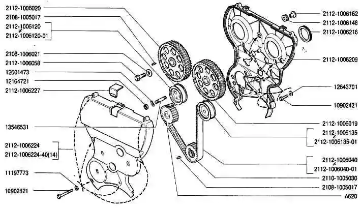
- The tension of the toothed belt is checked in the middle part of the run between the camshaft pulleys. The belt deflection must be 5.4 ± 0.2 mm under a load of 100 N (10 kgf).
- Assemble the parts in the reverse order.
Tightening torque of the bolt securing the alternator drive belt pulley: 97.9–108.8 N·m (9.90–11.10 kgf·m).


