We remove the engine flywheel when overhauling the engine or to replace the crown.
Preparing the car for the task. Disconnect the negative battery terminal.
Removing the transmission units
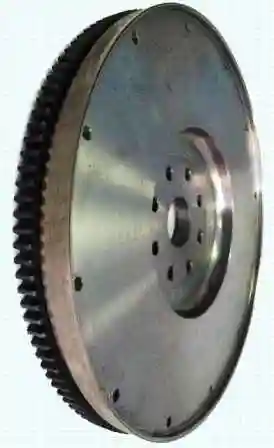
Remove the flywheel, for this:
(Models with a "wet" clutch): Drain the oil from the clutch housing by removing the plug from the bottom of it.
Using lock No. 3824591, we fix the flywheel from turning
We unscrew the two bolts located opposite each other
We install two guide pins M12x1.25x90 mm
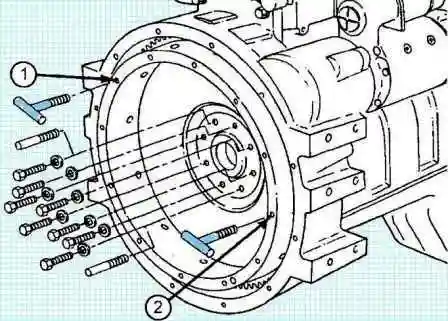
Determine the type and size of the bolts, install two T-handles in the flywheel holes (1) and (2)
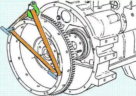
If the design provides for a clutch, the holes for the pressure plate mounting bolts can be made with metric or inch threads.
Don't make a mistake when choosing bolts.
Unscrew the remaining six flywheel mounting bolts
Remove the flywheel from the guide pins
Disassembly, inspection and repair of the flywheel
Check the condition of the gearbox input shaft support bearing pressed into the flywheel seat.
If there is a lot of play or seizing of the rolling elements, the bearing must be replaced.
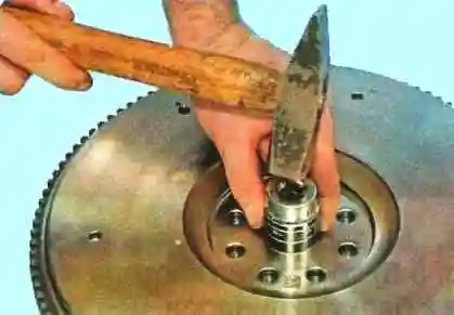
Remove the primary bearing with a mandrel and a hammer
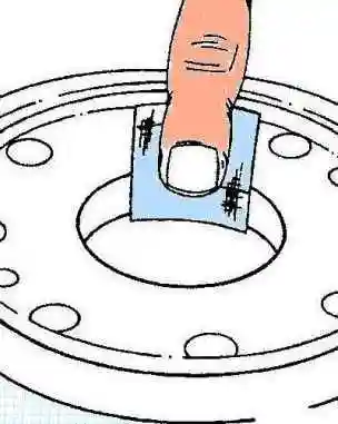
With fine sandpaper, we clean the surface for installing the bearing
Checking the surface of the flywheel for nicks and burrs
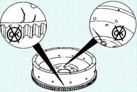
Small defects can be removed with sandpaper.
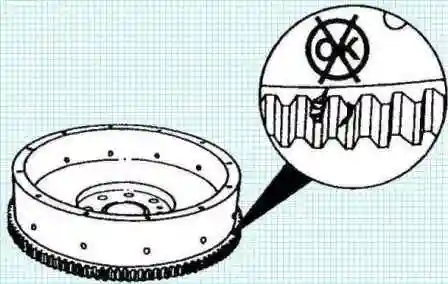
Check the flywheel ring gear for wear and damage to the teeth.
If necessary, we replace the flywheel ring gear, for this:
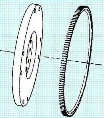
- use a copper rod to knock down the ring gear
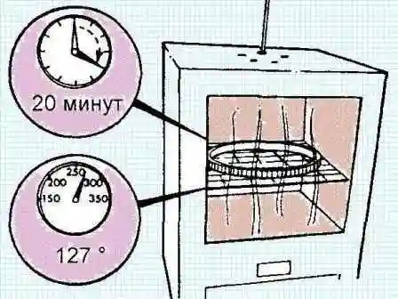
- heat the new ring gear for 20 minutes in an oven preheated to 127˚ C
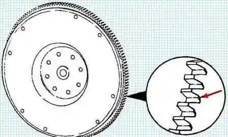
- install the ring gear on the flywheel with the side with a chamfer on the teeth to the crankshaft
Assembly
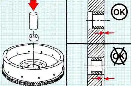
Installing the new primary bearing with a hammer and mandrel
Installing the flywheel
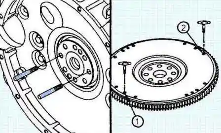
We install two guide pins M12x1.25x90 mm in the holes of the crankshaft flange opposite each other
We determine the type and size of the bolts, install two T-handles in the holes of the swingsika (1) and (2)
If the design provides for a clutch, the holes for the pressure plate mounting bolts can be made with metric or inch threads. Make no mistake when choosing bolts.
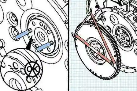
Check the rear end of the crankshaft and the flywheel flange for dirt and protruding notches and burrs
Installing the flywheel on the guide pins
Lubricate the threads of the bolts and washers with clean engine oil
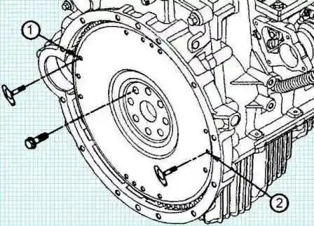
Install six bolts
Remove the T-handles and guide pins (1) and (2)
Installing the remaining bolts into the holes from which the guide pins were removed
We fix the crankshaft from turning using tool No. 3824591 for fixing the flywheel in a stationary position
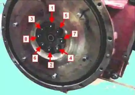
We tighten the bolts in the sequence shown in the figure.
Tightening torque: first stage - 30 Nm; second stage - turn 90˚
After that, we check the runout of the flywheel:
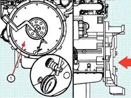
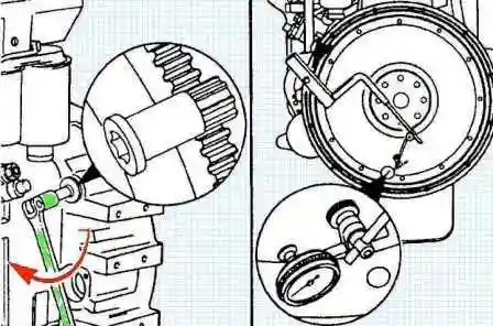
We determine the end runout of the flywheel (4) using a dial indicator (1) and a dial gauge tool (2)
- - install the fixture on the flywheel housing;
- - fix the sensor on the fixture;
- - install the indicator probe on the end of the flywheel;
- - install the indicator probe on the end of the flywheel at the radius indicated in the table, as close as possible to its outer diameter to measure the end (1) runout of the flywheel;
- - move the flywheel forward to select the axial clearance of the crankshaft. Set the indicator to zero;
- - turn the crankshaft one turn. We measure and record the runout of the flywheel at four equidistant points on its circumference.
Be sure to move the flywheel forward with each measurement to select the crankshaft end play
- define the full beat.
Total runout is defined as the difference between the maximum and minimum readings of the indicator at the four measurement points.
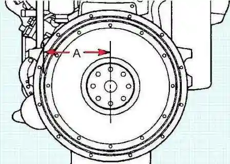
- measure the distance from the center of the flywheel to the indicator probe (A).
Maximum total runout
|
Flywheel radius, mm |
Maximum Full flywheel runout, mm |
|---|---|
|
101.6 |
0.140 |
|
127 |
0.130 |
|
152.4 |
0.156 |
|
177.8 |
0.182 |
|
203.2 |
0.208 |
|
228.6 |
0.234 |
|
254 |
0.260 |
If the flywheel runout is above maximum, the flywheel must be removed.
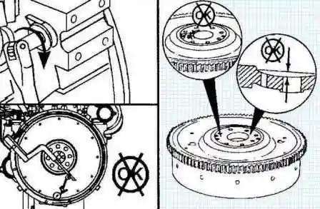
Check the contact surfaces of the flywheel and crankshaft for nicks, burrs and dirt.
Replace the flywheel if the runout is above the maximum.
After assembly, we install the transmission and all the details.


