After disassembled the engine, you need to thoroughly wash all the parts with gasoline and remove carbon deposits.
Before assembling the engine, it is necessary to inspect the cylinder block, cylinder head and all the main parts for assembling the engine.
Check the tightness of the cooling jacket of the block, to do this, plug all the holes in the block with wooden plugs, except for one, to which a hose for supplying compressed air can be connected.
Immerse the block in a bath of water and apply compressed air at a pressure of 1.5 atm.
Air bubbles will come out in places of leakage.
In the same way, check the tightness of the oil channels of the block.
If a leak is found, the block must be replaced.
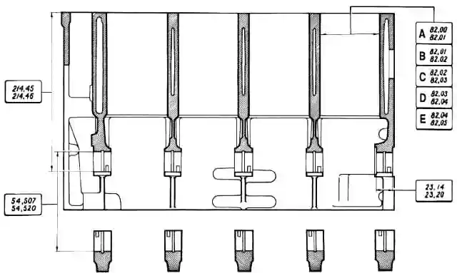
The main dimensions of the cylinder block of the VAZ-2123 engine
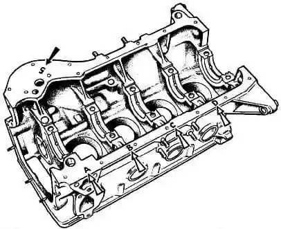
Marking the size class of cylinders on the block
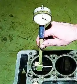
We measure the diameter of the cylinders with a bore gauge in four belts (at a distance of 8, 15, 50, 90 mm from the upper plane of the block) and in two directions (parallel and perpendicular to the axis of the crankshaft).
If wear exceeds 0.15 mm, it is necessary to bore the block to a repair size of 0.4 or 0.8 mm.
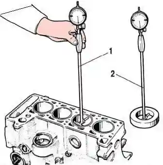
Scheme for measuring cylinders with an inside gauge
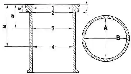
In zone 1, the cylinders show virtually no wear.
By the difference in measurements in the first and other zones, one can judge the amount of cylinder wear
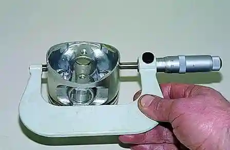
To determine the wear of the piston skirt, measure the diameter with a micrometer in a plane perpendicular to the axis of the piston pin, at a distance of 55 mm from the piston crown.
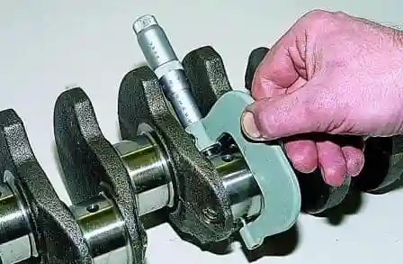
We measure the diameters of the connecting rod journals of the crankshaft with a micrometer
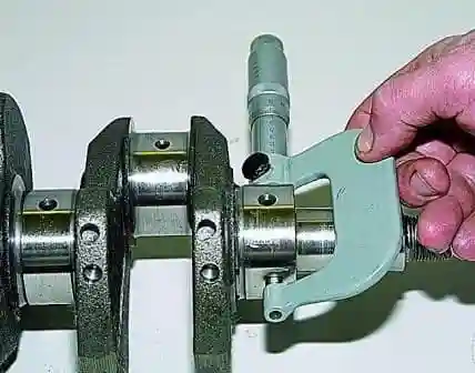
Measure the diameters of the main journals of the crankshaft
The crankshaft journals are ground to the nearest repair size if their ovality is greater than 0.03 mm, and also if there are scratches and marks on the journals.
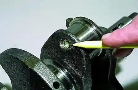
After grinding, remove the plugs from the oil channels and remove the remaining abrasive and deposits.
Installing new stubs
The surfaces of the flywheel mating with the crankshaft and with the clutch disc must be free of scratches, burrs and perfectly flat.
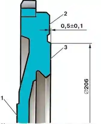
If there are scratches on the working surface 3 of the flywheel under the clutch disc, then you need to grind this surface, removing a layer of metal no more than 1 mm thick.
Then grind surface 2, maintaining a dimension of 0.5±0.1 mm and ensuring that surfaces 2 and 3 are parallel to surface 1.
The tolerance for non-parallelism is 0.1 mm.
After turning, install the flywheel on the mandrel, centering it on the mounting hole with emphasis on surface 1, check the runout of planes 3 and 2.
At the extreme points, the indicator should not show beats exceeding 0.1 mm.
Pay attention to the tightness of the ring gear and the condition of its teeth.
If the crown can be moved on the flywheel or the teeth are badly worn, replace the flywheel and crown assembly.
Replacing a crown is quite complicated and requires the performer to have certain skills, as well as the use of a special tool.
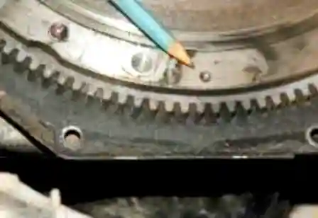
We install the flywheel and the removed components and parts in the reverse order of removal.
The flywheel can be mounted on the crankshaft in two opposite positions, determined by the location of the mounting holes.
At the factory, it is balanced with the crankshaft assembly, so it must be installed strictly in its original position.
For correct installation, the flywheel has a mark in the form of a conical hole, which should be oriented during installation in the same direction as the connecting rod journal of the 4th (1st) cylinder.
If, after removing the flywheel, the crankshaft was turned, set the piston of the 4th cylinder to the TDC position of the compression stroke, then another half turn and install the flywheel on the crankshaft, turning it with the mark vertically down.
Tighten the flywheel mounting bolts evenly crosswise with a torque of 60.96-87.42 Nm (6.22-8.92 kgf.m)


