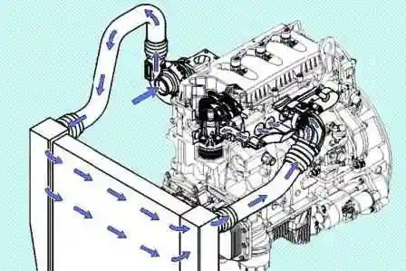
The air supply system of engines with a selective catalytic converter system consists of the following components:
- - air filter;
- - intake duct;
- - turbocharger;
- - charge air pipeline;
- - charge air cooler;
- - intake system heater.
Intake system resistance check
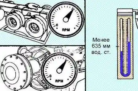
Install a vacuum or water gauge in the intake duct.
The pressure gauge adapter must be installed perpendicular to the air flow on a straight section of the channel, at a distance of one channel diameter from the turbocharger.
Note: On many automotive engines, intake system resistance can be measured by removing the mechanical clog indicator and replacing it with a vacuum or water gauge.
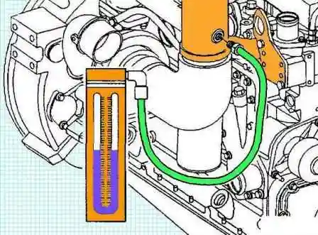
Run the engine at maximum fuel, maximum load and rated speed.
Read the pressure gauge.
Maximum intake system resistance 635 mm of water column
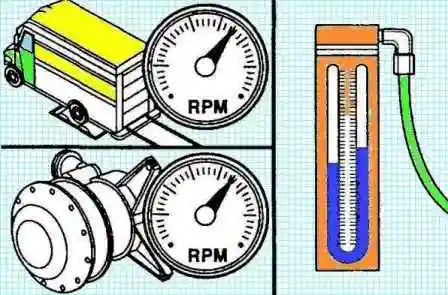
If the resistance is above normal:
- - Replace or clean the air filter.
- - Check the intake duct for damage.
Turbo system
Preliminary checks
Check the pipe connecting the compressor and the intercooler for breaks.
Note: if low-quality pipes are used, they may break when the maximum boost pressure is reached (for example, when driving along the highway at a speed close to the maximum, when driving uphill or when overtaking).
Especially from this malfunction, drivers of GAZ Valdai cars of the early years of production suffer.
In addition, the pipe of these cars has a complex shape and is not always available for sale.
As a compromise, the dealers offer to reduce the boost pressure, but at the same time lose power.
Some owners solved the problem radically by installing a homemade metal adapter on the nozzle, which reduces its diameter, which made it possible to install a more durable hose that has the same dimensions at both ends.
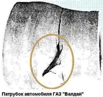
Attention: driving with a torn pipe causes the suction of dirty air, which will lead to a quick failure of the turbine and the cylinder-piston group.
Remove the air intake duct and air intake pipe from the turbocharger.
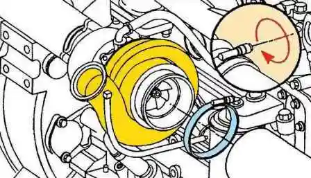
Check the compressor blades for damage.
Replace turbocharger if damaged.
If the compressor impeller is damaged, check the intake duct and filter element for damage.
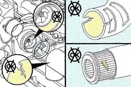
Repair any damage before starting the engine.
Remove the exhaust pipe from the turbocharger outlet fitting.
Check the turbine wheel for damage.
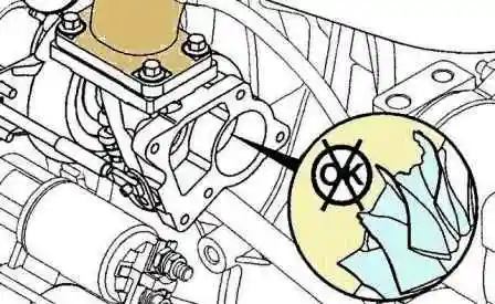
Check the turbocharger bypass valve control mechanism.
Check the lever pin.
Replace turbocharger if lever pin is worn beyond specification.
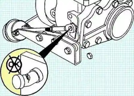
Check the valve and valve seat for cracks or erosion.
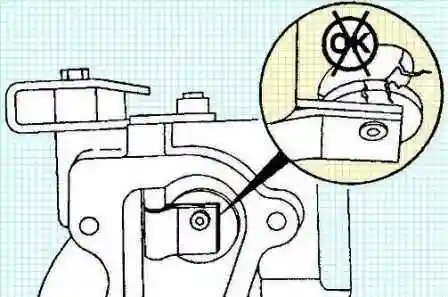
Replace the turbocharger if necessary.
Move the lever by hand to check the freedom of rotation of its axis.
Check for excessive play between axle and hub.
Replace the turbocharger if the axle and bushing are damaged or seized.
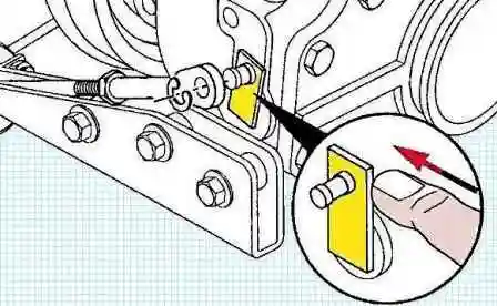
Check the turbocharger wastegate actuator.
Check the axial clearance of the turbocharger axle.
Install a dial indicator on the turbocharger axle.
Sink the axle.
Set the indicator to zero.
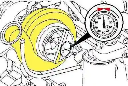
Move the axle to the indicator foot and determine the axial clearance.
Axial clearance 0.001 - 0076 mm
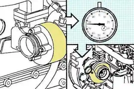
Check the radial clearance of the turbocharger axle bearing.
Gently press the compressor wheel against the housing and dipstick.
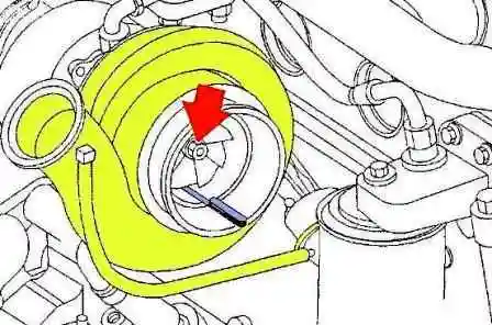
Write a note of the gap.
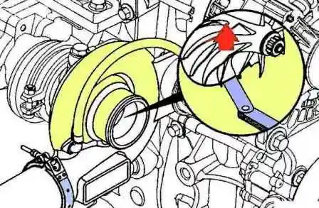
While holding the feeler gauge in the same position, move the compressor wheel away from the housing and re-measure the gap between them.
Subtract the smaller gap from the larger one. The result is the radial clearance of the bearing.
Radial clearance 0.396 - 0.602 mm
Repeat these steps for the turbine wheel.
Replace the turbocharger if the bearing radial clearance is not correct.
Check the turbocharger compressor inlet and outlet pipes for oil.
If oil is detected in both passages, check for an oil source upstream of the turbocharger.
Note:
- - The presence of traces of oil at the compressor inlet is allowed for engines with a closed crankcase ventilation system in which the crankcase cavity communicates with the intake air duct.
- - After a turbocharger failure or in other cases where oil or foreign particles enter the charge air system, it must be checked and cleaned.
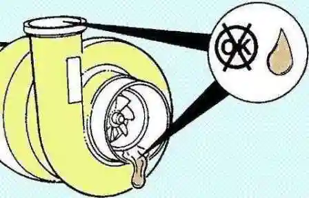
If deposits and/or oil leaks are found only in the outlet pipe, install the air intake duct and charge air cooler lines to check the resistance of the intake system.
Check the intake system resistance.
If there is no resistance in the inlet, replace the turbocharger.
Leak test
Add fluorescent dye (#3376891) to engine oil at a rate of one dose per 38 liters of oil.
Note: The fluorescent dye comes in 118 ml plastic bottles.
Let the engine run at low idle for 10 minutes.
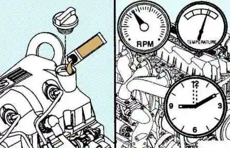
Turn off the engine.
Let the turbocharger cool down.
Remove the exhaust pipe from the turbocharger outlet fitting.
Remove the outlet pipe of the exhaust system.
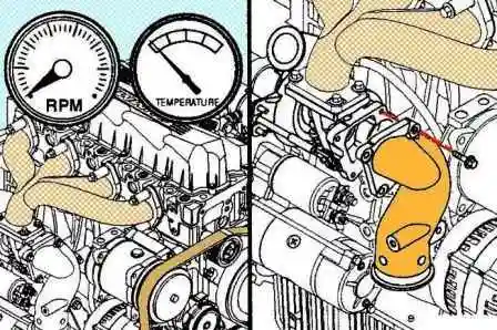
Using a high-intensity heat lamp, check the turbine outlet for oil.
Glowing dark blue indicates the presence of fuel in the oil, and yellow indicates an oil leak.
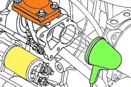
If oil is found in the turbine housing, remove the oil drain line and check if it is clogged.
If you find a blockage, remove it.
Install the drain line with new O-rings on the cylinder block.
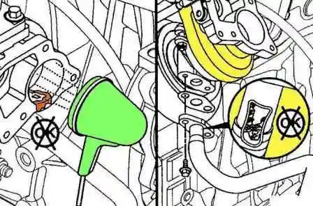
If there is no blockage in the drain line, remove the turbocharger.
Using a high-intensity heat lamp, check the turbine outlet for oil.
Glowing yellow indicates an oil leak from the engine.
In the event of a yellow glow, the turbocharger can be replaced and continue to operate.
A thin layer of oil on the casing and impeller of the turbine can not be removed, as it will burn itself out during engine operation.
All oily deposits in the turbine housing must be removed before installation with a clean rag.
If no yellow glow is found at the turbine inlet, replace the turbocharger.
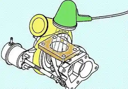
Install the exhaust manifold outlet.
Install the exhaust pipe on the turbocharger outlet fitting.
Install the inlet piping to the compressor inlet port of the turbocharger.


