


Cylinder block dismantling
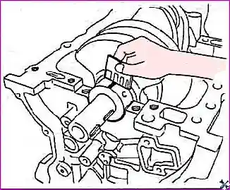
1. Check the side clearance between the lower connecting rod end and the corresponding crankshaft cheek.
Note:
- If the side clearance value exceeds the maximum permissible limit, replace the connecting rod together with its cap.
- If, after replacing the connecting rod together with its cap, the side clearance value still exceeds the maximum permissible limit, replace the crankshaft.
Nominal value: 0.1–0.25 mm.
Maximum permissible value: 0.35 mm.
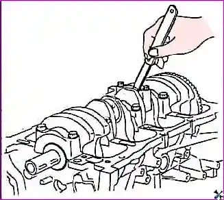
2. Check the oil clearance in the connecting rod bearings using a plastic gauge.
- a) Check that the alignment marks on the connecting rod and on the connecting rod cap are in line (to ensure correct assembly).
- b) Unscrew the connecting rod cap fastening bolts.
3. Remove the connecting rod cap and one of the connecting rod bearing shells.
- c) Clean the crankshaft journals and the bearing shells of oil and dirt.
- d) Cut a piece of plastic gauge of a length equal to the width of the bearing shell and place it parallel to the journal axis, away from the oil passage hole.
- e) Install the bearing shell and the connecting rod cap and tighten the fastening bolts to the nominal torque.
Caution: do not rotate the crankshaft during this procedure.
Tightening torque: 20 N·m + 90°.
- f) Remove the connecting rod cap and, using the scale printed on the gauge packaging, determine the bearing clearance.
Connecting rod bearing clearance:
- Nominal value: 0.025–0.043 mm.
- Maximum permissible value: 0.06 mm.
Note: do not subject the bearing or the connecting rod cap to machining to adjust the clearance.
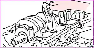
If the clearance exceeds the maximum, replace the bearings. If necessary, replace the crankshaft.
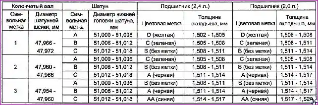
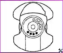
Note: when replacing the connecting rod bearing shells, select them according to the table “Connecting rod bearing shell selection” in accordance with the crankshaft dimension group (symbol mark), the connecting rod dimension group (symbol mark) and the colour mark of the connecting rod bearing shells.
Table. Connecting rod bearing shell selection.
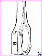
Connecting rod dimension group mark.
Bearing shell dimension group mark.
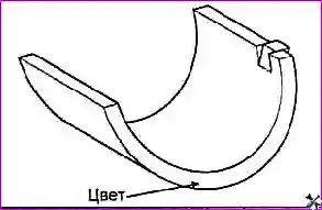
Connecting rod journal dimension group mark.
3. Measure the crankshaft axial clearance by moving it back and forth with a screwdriver. If the axial clearance exceeds the maximum permissible value, replace the bearing thrust half-rings and/or the bearing shells.
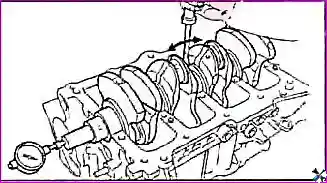
Axial clearance:
- Nominal value: 0.07–0.25 mm.
- Maximum permissible value: 0.30 mm.
4. Check the oil clearance in the main bearings using a plastic gauge.
- a) Clean the surfaces of the cylinder block and the main bearing caps, the crankshaft main journals and the bearing shells of oil, grease and other dirt deposits.
- b) Carefully place the crankshaft in the cylinder block.
- c) Cut a piece of calibrated plastic wire whose length matches the width of the journal, then place it on the crankshaft journal along the crankshaft axis.
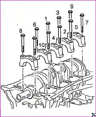
- d) Carefully install the bearing cap and tighten the fastening bolts in the sequence shown in the figure.
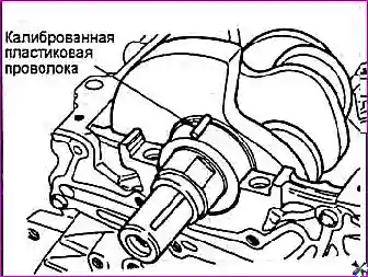
Caution: do not rotate the crankshaft during this procedure.
Tightening torque: 26.5 N·m + 45°.
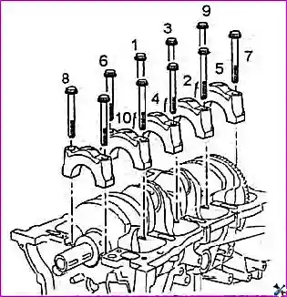
- e) Unscrew the crankshaft main bearing cap fastening bolts in the sequence shown in the figure, then carefully remove the cap.
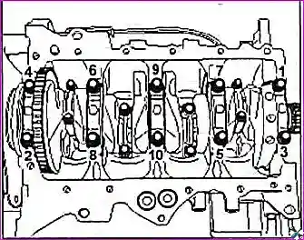
- f) Measure the width of the crushed calibrated plastic wire at its widest part, using the scale printed on the plastic gauge packaging.
Main bearing clearance:
Nominal value:
- 2.0 l from 2009: 0.020–0.038 mm.
- Others: 0.026–0.048 mm.
Maximum permissible value: 0.05 mm.
Note: do not subject the bearing or the bearing cap to machining to adjust the clearance.
If the clearance exceeds the maximum, replace the bearings. If necessary, replace the crankshaft.
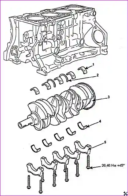
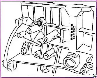
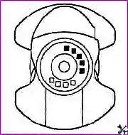
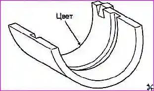
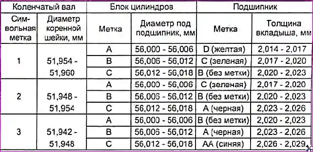
- g) When replacing the main bearing shells, select them in accordance with the colour mark of the main bearing shells, the crankshaft bed dimension group (symbol marks on the cylinder block) and the crankshaft dimension group (symbol marks) (see the table “Main bearing shell selection”).
Mark of the dimension group of the inner diameter of the crankshaft main bearing bed.
Main journal dimension group mark.
Bearing shell dimension group mark.
Flywheel (models with manual transmission)
- 1. Check the condition of the contact surface of the flywheel with the driven clutch disc (no uneven wear or damage). Replace the flywheel if the surface is damaged or significantly worn.
- 2. Measure the runout of the contact surface of the flywheel with the driven clutch disc.
- Nominal value: 0.10 mm.
- Maximum permissible value: 0.13 mm.
3. Check the condition of the flywheel ring gear (no damage, cracks or significant wear) and replace it if necessary.
Torque converter drive plate (models with automatic transmission)
Check the torque converter drive plate for deformation, damage and cracks. Replace it if necessary.
Table. Main bearing shell selection.
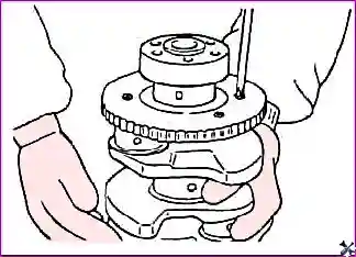
Crankshaft position sensor rotor
- 1. Remove the crankshaft position sensor rotor.
- 2. Check the crankshaft position sensor rotor for damage, cracks and wear. Replace the sensor rotor if necessary.
- 3. Check the clearance between the sensor rotor tooth and the sensor tip using a depth gauge.
Nominal value: 0.5–1.1 mm.
Note:
- Measure the distance from the top of the crankshaft position sensor rotor tooth to the mounting surface for the sensor on the cylinder block.
- Measure the length of the crankshaft position sensor tip as the distance between the end face of the sensor tip and the sensor seating plane.
- Calculate the clearance as the difference between the specified values.
Checking
- 1. Check the cylinder block for chips, corrosion, scale deposits and rust. In addition, check for cracks and other damage. Replace the cylinder block if significant defects are found.
- 2. Using a straight edge and a flat feeler gauge, check the warpage (non-flatness) of the cylinder block mating surface for the gasket. Before checking, make sure that the cylinder block surface is cleaned of old gasket residues and foreign particles.
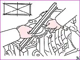
Nominal value: 0.05 mm or less.
3. Measure the cylinder diameter using a bore gauge in three height bands in the “A” and “B” directions. Take measurements at the points shown in the figure.
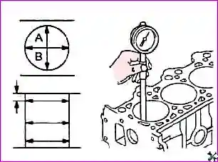
- (1) Piston TDC (stopping point of compression ring No. 1);
- (2) mid-stroke of the piston;
- (3) Piston BDC.
Nominal cylinder diameter:
- 2.0 l: 86.00–86.03 mm.
- 2.4 l: 88.00–88.03 mm.
Maximum permissible taper (deviation from cylindricity): 0.01 mm or less.
4. If either the ovality or the taper of a cylinder exceeds the maximum permissible value, or if the cylinder bore has scratches or scuffing marks, the cylinder block bores should be rebored to the appropriate repair size and honed. After repairing the cylinder block, install pistons and piston rings of the appropriate repair size.
Maximum permissible ovality and taper of the cylinder: 0.01 mm.
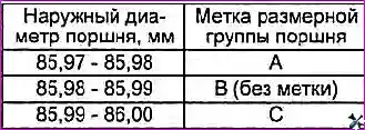
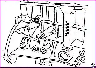
5. Determining the cylinder diameter and the piston diameter by the marks.
a) Check the mark for determining the cylinder diameter on the lower part of the cylinder block.
Table. Determining the cylinder diameter by the marks (2.0 l).
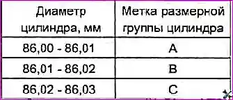
Table. Determining the cylinder diameter by the marks (2.4 l).
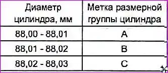
Table. Determining the piston outer diameter by the marks (2.0 l).
Cylinder dimension group mark.
b) Check the mark for determining the piston outer diameter on the piston crown.
Table. Determining the piston outer diameter by the marks (2.4 l).
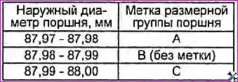
Piston dimension group mark.
Dismantling the “piston–connecting rod” assembly
Caution: arrange the removed parts (connecting rods, connecting rod caps, connecting rod bearing shells) as a set, in the order corresponding to the cylinder numbers, to ensure correct subsequent assembly.
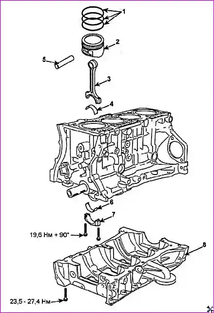
- When removing parts, refer to the figure “Piston and connecting rod”.
- When removing parts, pay attention to the following operations.
- a) Unscrew the connecting rod cap fastening bolts, then remove the connecting rod cap and the lower connecting rod bearing shell.
- b) Push the piston and connecting rod assembly out of the cylinder block towards the cylinder head gasket surface.
Caution: be careful when removing the piston with the connecting rod assembly, do not strike the cylinder surface or the crankshaft journal with the connecting rod.
- c) Mark the cylinder number on the side surface of the connecting rod to facilitate subsequent assembly.
Checking the condition of the piston and connecting rod
- 1. Check each piston for scratches, scuffing, wear and other defects. Replace the piston if defects are present.
- 2. Check each piston ring for breakage, damage or significant wear. Replace defective rings. If the piston needs to be replaced, its piston rings should also be replaced at the same time.
- 3. Check the clearance between the piston and the cylinder.
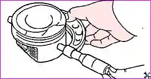
a) Using a micrometer, measure the piston skirt diameter at a distance of 47 mm from the piston crown surface (below the level of the piston ring grooves) in the direction perpendicular to the piston pin axis, as shown in the figure.
Nominal piston diameter:
- 2.0 l: 85.97–86.00 mm.
- 2.4 l: 87.97–88.00 mm.
b) Measure the cylinder diameters in the direction of the engine axis (see above).
c) Measure the cylinder diameter using a bore gauge in three height bands in the “A” and “B” directions. Take measurements at the points shown in the figure.
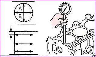
- (1) Piston TDC (stopping point of compression ring No. 1);
- (2) mid-stroke of the piston;
- (3) Piston BDC.
Nominal cylinder diameter:
- 2.0 l: 86.00–86.03 mm.
- 2.4 l: 88.00–88.03 mm.
Maximum permissible taper (deviation from cylindricity): 0.01 mm or less.
d) Find the difference between the measurement results of the piston diameter and the cylinder diameter.
Clearance between the cylinder and the piston:
Nominal:
- 2.0 l: 0.015–0.035 mm.
- 2.4 l: 0.025–0.040 mm.
- Maximum: 0.080 mm.
If the clearance exceeds the maximum, replace all four pistons. If necessary, replace the cylinder block.
Note: when using a new cylinder block, use a piston with the same mark (number) as the cylinder diameter.
4. Measure the clearance between the piston ring and the piston ring groove. If the measured clearance exceeds the maximum permissible value, install a new piston ring and re-measure the clearance. If the measured clearance again exceeds the maximum permissible value, replace the piston and rings as a set. If the measured clearance is less than the maximum permissible value, replace only the piston rings.
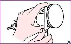
Clearance between the piston ring and the piston ring groove:
Nominal value:
2.0 l:
- Compression ring No. 1: 0.05–0.08 mm.
- Compression ring No. 2: 0.04–0.08 mm.
- Oil scraper ring: 0.06–0.15 mm.
2.4 l:
- Compression rings No. 1 and No. 2: 0.03–0.07 mm.
- Oil scraper ring: 0.06–0.15 mm.
Maximum permissible value:
- Compression rings No. 1 and No. 2: 0.10 mm.
- Oil scraper ring: 0.20 mm.
5. To measure the piston ring end gap, install the piston ring into the cylinder bore. Position the ring at right angles to the cylinder wall generatrix, carefully moving it down using the piston. Measure the ring end gap using a flat feeler gauge. If the measured clearance exceeds the maximum permissible value, replace the piston ring.
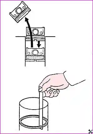
Piston ring end gap:
Nominal value:
- Compression ring No. 1: 0.15–0.30 mm.
- Compression ring No. 2: 2.0 l — 0.37–0.52 mm; 2.4 l — 0.30–0.45 mm.
- Oil scraper ring: 0.20–0.70 mm.
Maximum permissible value:
- Compression ring No. 1: 0.6 mm.
- Compression ring No. 2: 0.7 mm.
- Oil scraper ring: 0.8 mm.
6. When replacing piston rings without reboring the cylinders to the repair size, check the ring end gap at a point located in the lower part of the cylinder (the minimum wear zone).
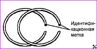
Note: the repair size identification mark is located on the upper part of the piston ring near the ring end gap.
7. Check the piston pin.
- a) Try to insert the piston pin into the piston bore with thumb force. Resistance should be felt. Replace the piston pin if it enters the bore easily or if there is significant play. Replace the piston pin if defects are present.
- b) Measure the piston pin diameter.
Nominal value: 21.001–21.006 mm.
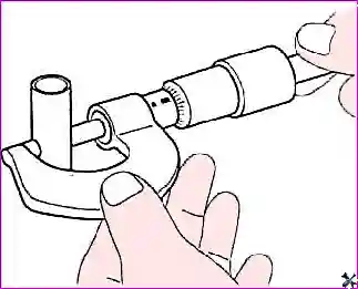
- c) Determine the clearance between the piston pin and the piston (in the piston bosses).
Nominal value: 0.010–0.020 mm.
- d) Determine the difference between the piston pin diameter and the diameter of the bore in the upper connecting rod end for the piston pin.
Nominal value: 0.016–0.032 mm.
- 8. Replace the connecting rod if the end surface of the upper or lower end is damaged.
- 9. If the surface of the bore for the piston pin in the upper connecting rod end is significantly worn, replace the connecting rod.
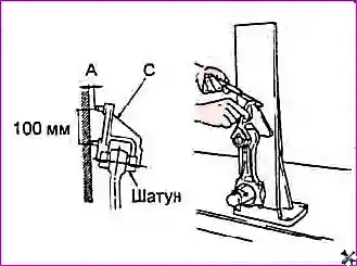
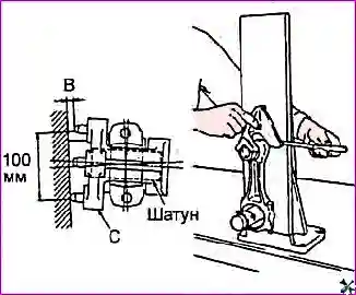
10. Using a special connecting rod checking device, check the bending and twisting of the connecting rod. If the measured value exceeds the maximum permissible value, straighten the connecting rod using a press. If necessary, replace the connecting rod.
Maximum permissible value (per 100 mm of part length):
- Bending: 0.05 mm.
- Twisting: 0.10 mm.
Repair (piston pin replacement)
1. Using special tools, dismantle and assemble the piston and connecting rod assembly.
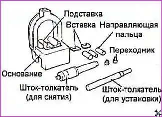
- 2. The piston pin is press-fitted into the upper connecting rod end, and the piston slides on it at a certain temperature.
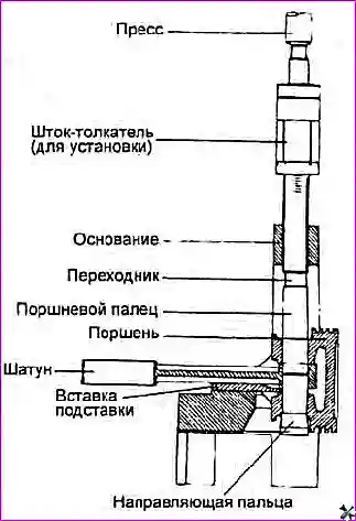
- 3. The special tool set consists of a base with a support and inserts, guides, adapters, a removal push rod and an installation push rod. When removing or installing the piston pin, the piston is held on the base of the fixture. The fixture guides facilitate the positioning of the piston pin during its removal and installation, when the connecting rod rests on the support inserts.
- 4. To remove the piston pin, place the piston on the base and position the connecting rod on the support insert. Insert the removal push rod through the arc of the upper part of the base into the piston pin and extract the pin using a press.
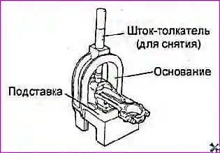
- 5. When installing a new pin, it is necessary to install the appropriate support insert to support the connecting rod.
- 6. Position the upper connecting rod end inside the piston. On one side of the piston, insert the appropriate guide through the piston and the connecting rod, then slightly seat the guide by hand so that it is held by the piston. On the other side of the piston, insert the piston pin and place the piston and connecting rod together on the base of the fixture so that the pin guide is at the bottom.
Note: the guide is necessary for centring the connecting rod relative to the piston bosses. If the assembly is correct, the pin guide will stand exactly in the centre of the arc opening of the upper part of the base and touch the support insert. If a pin guide of the wrong size is used, the piston (and connecting rod) and the piston pin will not be on the same axis as the base opening.
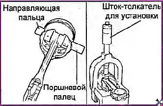
7. Insert the installation push rod through the arc opening of the upper part of the base until it stops against the adapter on the piston pin and, using a hydraulic press, drive the pin into the piston and the upper connecting rod end. Continue press-fitting until the pin guide falls out from the bottom of the base and the push rod rests against the arc of the upper part of the base.
Caution: do not exceed the maximum permissible force when press-fitting the piston pin at the moment when the push rod rests against the arc of the upper part of the base.
Maximum permissible press-fitting force: 15,000 ± 5,000 N.
Checking the crankshaft
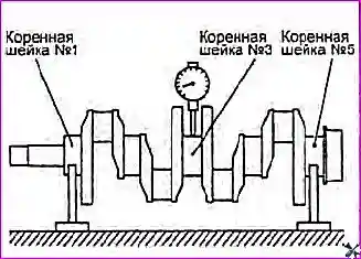
1. Check the bending (runout at the middle journal) of the crankshaft.
- a) Place the crankshaft on prisms (on main journal No. 1 and main journal No. 5).
- b) Using a dial indicator, measure the shaft runout at the central main journal (No. 3).
Crankshaft runout:
- Nominal: 0.02 mm or less.
- Maximum permissible: 0.05 mm.
Note: the actual crankshaft runout is equal to half the value indicated by the dial indicator when the shaft is rotated one full turn.
- c) If the measured runout exceeds the maximum permissible value, replace the crankshaft.
- 2. Check the crankshaft main and connecting rod journals for damage (scuffing and seizure marks), excessive wear and cracks. In addition, check the oil passage holes for blockage. Repair or replace the faulty part.
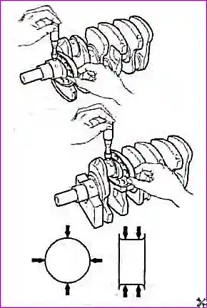
- 3. Check the taper and ovality of the crankshaft main and connecting rod journals.
Nominal value:
- Main journal diameter: 51.942–51.960 mm.
- Connecting rod journal diameter: 47.954–47.972 mm.
Taper and ovality of the main and connecting rod journals: 0.05 mm or less.
Cylinder reboring
Caution: rebore all cylinders to the same repair size. Do not rebore only one cylinder to the repair size.
- 1. If there is a ridge (stepped wear) around the cylinder circumference in its upper part, remove it using a special tool.
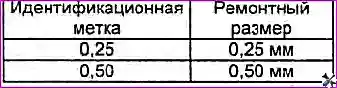
- 2. Based on the largest cylinder diameter of the engine being repaired, obtained as a result of the measurements, determine the repair size number of the pistons.
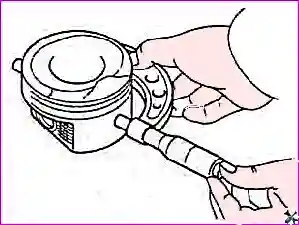
3. Measure the outer diameter of the piston intended for use at the point shown in the figure.
Note: standard piston diameter measurements are taken at a distance of 47 mm from the piston crown surface in the plane perpendicular to the piston pin axis.
4. Based on the measured value of the piston outer diameter, calculate the cylinder reboring diameter.
Cylinder reboring diameter = piston outer diameter + (clearance between piston and cylinder) − 0.01 mm (honing allowance).
5. Rebore all cylinders to the calculated diameter.
Caution: to prevent thermal deformation during reboring, rebore the cylinders in the following sequence: No. 2, No. 4, No. 1, No. 3.
6. Hone the cylinders to the final finishing size (piston outer diameter + clearance between piston and cylinder).
Caution: to prevent thermal deformation during honing, hone the cylinders in the following sequence: No. 2, No. 4, No. 1, No. 3.
7. Check the clearance between the piston and the cylinder (the established limit for new parts).
Nominal value: 0.02–0.04 mm.
Note:
- Check that all pistons being installed are of the same repair size.
- The maximum permissible clearance value for a run-in piston-cylinder pair is not more than 0.085 mm.
Assembly
1. Install the upper main bearing shells into the crankshaft bed on the cylinder block. The upper crankshaft main bearing shell has a groove for lubricant supply.
Note: be careful, install the main bearing shells in accordance with the cylinder numbers.
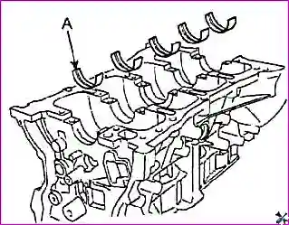
- 2. Install the lower bearing shells (without grooves) into the main bearing caps.
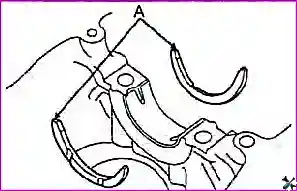
- 3. Install the thrust half-rings on both sides of main bearing No. 3 with the grooves facing outwards.
- 4. Apply engine oil to the crankshaft main journals and install the crankshaft.
- 5. Install the main bearing caps.
- a) When installing, the caps must be positioned so that the cap arrows point towards the crankshaft pulley and the cap numbers correspond to the shaft journal numbers.
- b) Apply engine oil to the bolt threads and under their heads.
- c) Tighten the main bearing cap fastening bolts to the nominal torque in the sequence shown in the corresponding figure.
Caution: the cap fastening bolts should be tightened gradually in two or three passes with increasing torque, then tightened to the nominal torque and turned through the specified angle.
Tightening torque: 26.5 N·m + 45°.
6. Check the smooth rotation of the crankshaft and measure the shaft axial clearance.
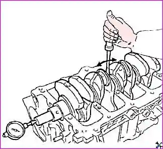
Axial clearance:
- Nominal value: 0.07–0.25 mm.
- Maximum permissible value: 0.30 mm.
7. Assemble the connecting rod and piston group.
a) Install the oil scraper ring expander.
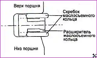
b) Install the upper scraper of the oil scraper ring. To install the scraper, first place one end of the scraper between the expander and the piston groove, then, holding the end of the scraper, press the scraper with your finger to guide it into the groove, as shown in the figure.
Caution: do not use a piston ring expander when installing the oil scraper ring scrapers.
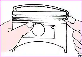
- c) Install the lower scraper of the oil scraper ring in accordance with the procedure given in point b).
- d) Apply engine oil to the piston and the piston ring grooves around the entire circumference.
Note: make sure that the end gaps of the scrapers and expanders of the oil scraper rings are positioned as shown in the figure.
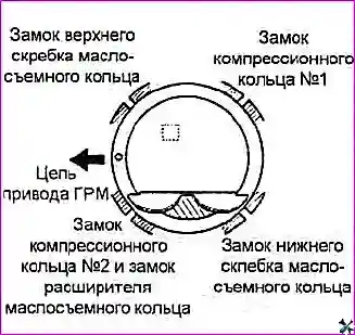
- e) Using a piston ring expander, install compression ring No. 2 and compression ring No. 1 with the identification mark towards the piston crown (upwards).
- f) Position the ring end gaps as far apart as possible. Make sure that the end gap of any ring is not on the piston pin axis or in the direction perpendicular to that axis.
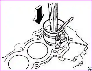
2. Using a special device, securely fix the piston rings on the piston before installing the piston assembly into the cylinder.
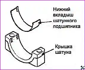
- 8. Install the upper bearing shells into the connecting rods.
- 9. Install the lower bearing shells into the connecting rod caps.
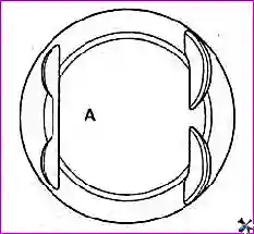
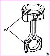
10. When installing, make sure that the “front” mark (A) on the piston and the “front” identification mark on the connecting rod face towards the front of the engine (towards the timing chain).
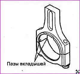
11. When installing the connecting rod cap, make sure that the cylinder number marks (made during dismantling) on the connecting rod and the connecting rod cap coincide. When installing a new connecting rod, make sure that the bearing shell locating grooves in the connecting rod cap and the connecting rod are on the same side.
12. During assembly, the connecting rod cap fastening bolts should be tightened as follows:
- a) Apply oil to the threads of the fastening bolts and to the contact points of the bolts with the connecting rod (under the bolt head).
- b) Tighten the connecting rod cap fastening bolts to the nominal tightening torque.
Tightening torque: 29 N·m + (88°–92°).
Caution:
- Do not reinstall used (removed during dismantling) connecting rod cap fastening bolts.
- When installing new connecting rod cap fastening bolts, do not tighten them more than three times.
13. Install the crankcase.
- a) Clean the mating surfaces of the cylinder block and the crankcase of old sealant residues.
- b) Degrease the surface for applying the sealant on the crankcase flange, as well as the mating surface on the cylinder block.
- c) Apply the specified sealant in a continuous bead of 3–4 mm diameter into the groove on the crankcase flange.
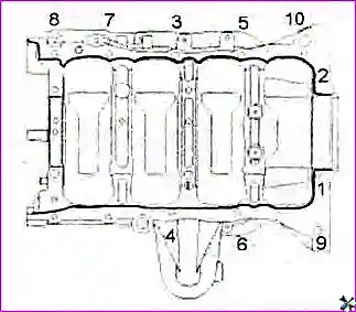
Sealant: Three Bond 1217H.
Caution:
- In the area of the crankcase fastening bolt holes, the sealant should be applied along the inner line from the hole.
- Do not allow the sealant to squeeze out beyond the crankcase flange on the crankshaft side.
- Secure the crankcase within 5 minutes after applying the sealant. After installing the crankcase, wait at least one hour before starting the engine.
- d) Tighten the crankcase fastening bolts (gradually, in several passes up to the nominal torque).
Tightening torque: 19–27 N·m.


