


We covered the removal and installation of the cylinder head in the previous article.
Dismantling
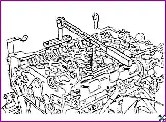
1. Using a valve spring compressor, extract the split collets from the valve spring retainer. Then remove the valve spring retainer, the valve spring, the valve spring seat and the valve itself.
Note:
- Keep the parts for each valve separately as a set so that they are not mixed up during installation.
- Lay out the valves of the camshafts in the order corresponding to their installation location.
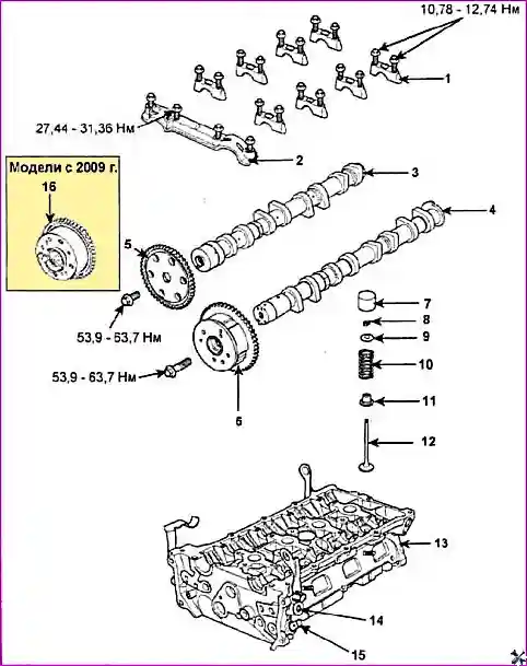
2. Using pliers, remove the valve stem seals.
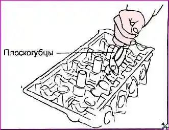
Note: reuse of valve stem seals is not permitted.
3. Using a magnetic rod, remove the valve spring seat.
Checking
Camshafts
1. Check the camshaft journals for wear. If the shaft journals are significantly worn, replace the camshaft.
Camshaft bearing journal diameter: 22.964–22.980 mm.
2. Check the protruding part of the camshaft cams for damage. If the shaft cams are damaged or their wear exceeds the permissible value, replace the camshaft.
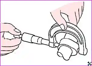
Camshaft cam height:
Inlet:
- models up to 2009: 43.70–43.90 mm;
- models from 2009: 44.10–44.30 mm.
Exhaust: 44.90–45.10 mm.
3. Check the surface of the back part of the camshaft cams for damage or significant wear; replace the shaft if necessary.
4. Checking the camshaft oil clearance using a plastic gauge.
Note: the use of this method greatly simplifies the procedure for determining the clearances in the camshaft bearings.
- a) Clean the surfaces of the cylinder head bed, the camshaft bearing caps and the camshaft journal of oil and grease deposits.
- b) Carefully place the camshaft in the cylinder head.
- c) Cut a piece of plastic gauge of a length matching the width of the journal, then place it on the camshaft journal along the camshaft axis.
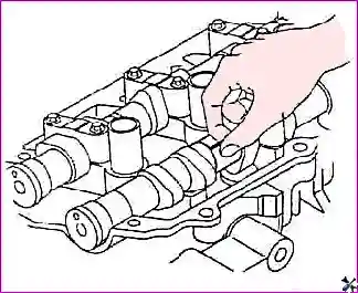
- d) Carefully install the camshaft bearing caps on the cylinder head and tighten the fastening bolts to the nominal torque in two or three passes in the order shown in the figure.
Tightening torque:
- M6 bolt: 11–13 N·m;
- M8 bolt: 28–31 N·m.
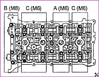
- e) Unscrew the fastening bolts in two or three passes in the reverse order of tightening and carefully remove the camshaft bearing caps.
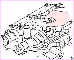
- f) Measure the width of the crushed calibrated plastic wire at its widest part, using the scale printed on the plastic gauge packaging.
Clearance in the camshaft bearings:
Models up to 2009:
Nominal value:
- journal No. 1: 0.020–0.057 mm;
- the rest: 0.045–0.082 mm.
Maximum permissible value:
- journal No. 1: 0.09 mm;
- the rest: 0.12 mm.
Models from 2009:
Nominal value:
Inlet:
- journal No. 1: 0.022–0.057 mm;
- the rest: 0.045–0.082 mm.
Exhaust:
- journal No. 1: 0–0.032 mm;
- the rest: 0.045–0.082 mm.
Maximum permissible value:
Inlet:
- journal No. 1: 0.09 mm;
- the rest: 0.12 mm.
Exhaust: 0.12 mm.
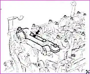
5. (Models from 2009.) Selection of the bearing shell for journal No. 1 of the exhaust valve camshaft.
a) Check the mark on the cap of journal No. 1 of the camshaft bearings.
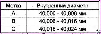
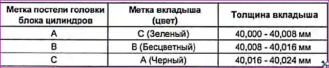
b) When replacing the bearing shells, select them according to the table “Selection of the bearing shell for journal No. 1 of the exhaust valve camshaft” in accordance with the dimension group (symbol mark) of the cylinder head bed and the colour mark of the bearing shells.
Oil clearance of journal No. 1 (exhaust): 0–0.032 mm.
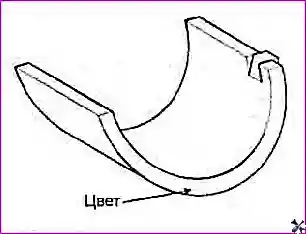
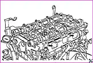
6. Measure the camshaft axial clearance and, if the measured value exceeds the upper limit of the nominal value range, replace the camshaft. If necessary, replace the bearing caps and the cylinder head.
Nominal value: 0.04–0.16 mm.
7. Install the camshaft on the supports (on the outer bearing journals). Measure the shaft runout at the middle journal. If the runout exceeds the maximum permissible value, replace the camshaft.
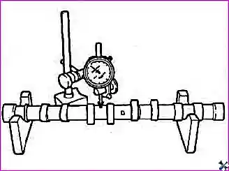
Camshaft runout:
- nominal value: less than 0.03 mm;
- maximum permissible value: 0.08 mm.
Table. Selection of the bearing shell for journal No. 1 of the exhaust valve camshaft.
Cylinder head
- 1. Check the cylinder head for cracks, damage and traces of coolant leakage. If cracks are found, replace the cylinder head.
- 2. Clean the cylinder head completely of scale, carbon deposits and remnants of the old sealant and gasket. After cleaning the oil passages, blow them through with compressed air to check that they are not blocked.
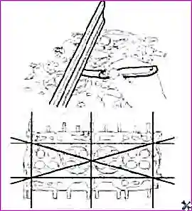
- 3. Check the non-flatness of the cylinder head mating surface in the directions shown in the figure. If the non-flatness exceeds the maximum permissible value in any direction, either replace the cylinder head or lightly grind the cylinder head mating surface.
Non-flatness of the cylinder head mating surface:
- nominal value: less than 0.03 mm;
- maximum permissible value: 0.05 mm.
Non-flatness of the cylinder head mounting surface for the manifolds:
- nominal value: not more than 0.15 mm;
- maximum permissible value: not more than 0.30 mm.
Valves
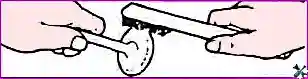
1. Using a wire brush, thoroughly clean the valve.
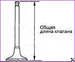
2. Check each valve for wear, damage and deformation of the valve head and stem. Replace the valve if necessary. If dents have formed on the end of the valve stem or there is significant wear, machine the end of the valve stem if necessary. The thickness of the layer removed during machining of the valve stem end must be minimal. In addition, machine the working chamfer of the valve seat.
Valve length:
Nominal value:
- inlet: 113.18 mm;
- exhaust: 105.89 mm.
Maximum permissible value:
- inlet: 112.93 mm;
- exhaust: 105.59 mm.
3. Replace the valve if the thickness of the valve head is less than the maximum permissible value.
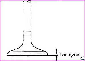
Valve head thickness:
Nominal value:
- inlet valve: 1.02 mm;
- exhaust valve: 1.09 mm.
Maximum permissible value:
- inlet valve: 0.8 mm;
- exhaust valve: 1.0 mm.
Valve springs
1. Check the length of each valve spring in the free state. If the spring length is less than the maximum permissible value, replace the valve spring.
Free length of the spring: 47.44 mm.
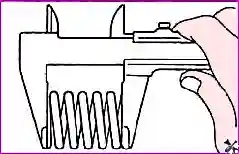
2. Using a square, check the deviation of the axis of each spring from the perpendicular to the supporting surface (non-perpendicularity). If the non-perpendicularity exceeds the maximum permissible value, replace the valve spring.
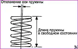
Deviation of the spring axis (non-perpendicularity):
- nominal value: 1.5° or less;
- maximum permissible value: not more than 3°.
Checking the valve seat
Check the valve seat for traces of overheating and uneven contact with the working chamfer of the valve head. If necessary, either restore (machine) or replace the valve seat. Before restoring the valve seat, check the valve guide for wear. If the guide is worn, first replace the guide, then restore the valve seat.
Valve guides
Check the clearance between the valve guide and the valve stem (at several points along the length). If the clearance exceeds the maximum permissible value, replace the valve guide with a guide of the next repair size.
Clearance between the valve guide and the valve stem:
Nominal value:
- inlet: 0.020–0.047 mm;
- exhaust: 0.030–0.054 mm.
Maximum permissible value:
- inlet: 0.07 mm;
- exhaust: 0.09 mm.
Inner diameter of the valve guide: 5.500–5.512 mm.
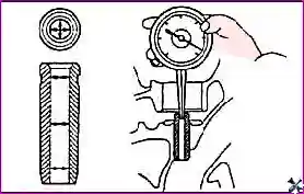
Nominal valve stem diameter:
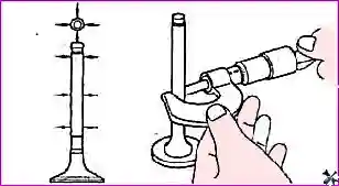
- inlet: 5.465–5.480 mm;
- exhaust: 5.458–5.470 mm.
Checking the valve tappets
- 1. Check the condition of the valve tappet (absence of damage and deformation).
- 2. The procedure for checking and adjusting the clearance in the valve train is given in the article “Adjusting the clearances”.
Repair
Replacing the valve guide
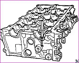
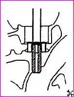
1. Using a special tool (valve guide installation drift), press the old valve guide out of the cylinder head in the direction of the gasket surface.
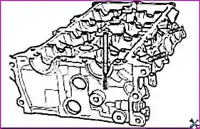
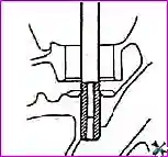
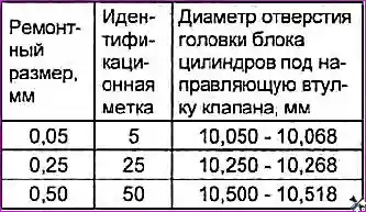
2. Bore out the hole in the cylinder head to install the valve guide of the corresponding repair size (enlarged diameter).
Nominal hole diameter: 10.000–10.018 mm.
Table. Repair sizes of valve guides.
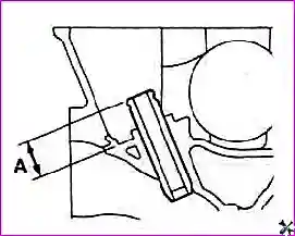
3. Using a special tool (valve guide installation drift), press in the new valve guide so that its protrusion from the end to the seating surface of the valve spring seat is equal to “A” (see figure). The guide should be pressed in from the upper surface of the cylinder head.
Valve guide length: 43.8–44.2 mm.
Note: do not install the valve guide if it does not correspond to the repair size.
- 4. After installing the valve guide, insert a new valve and check that the clearance between the guide and the valve stem corresponds to the nominal value.
- 5. After replacing the valve guide, check the correct seating of the valve in its seat. If necessary, machine the valve seat.
Reconditioning the valve
- 1. Grind the valve until carbon deposits and scratches are removed.
- 2. Make sure that the working chamfer angle corresponds to the nominal value.
Valve working chamfer angle: 45.25°–45.75°.
Caution: grinding of the valve must be minimal.
- If the valve head thickness after grinding is less than the maximum permissible value, replace the valve.
- After grinding, lap the valve and the valve seat to ensure a correct contact pattern.
Lapping the valve to its seat
1. Apply a thin layer of lapping paste evenly to the seating surface of the valve seat.
Caution:
- Do not allow the lapping paste to get onto the valve stem.
- First use medium-grit paste (grit 120–150), then fine lapping paste (grit above 200). For even application of the lapping paste, use a mixture of paste and a small amount of engine oil.
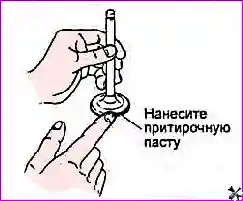
2. Press the valve against its seat several times with a blow, gradually turning the valve using a special tool.
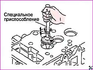
- 3. Wash the lapping paste off the valve seat with kerosene.
- 4. Apply a thin layer of engine oil to the contact surface.
- 5. Check the contact pattern of the valve with its seat. If necessary, restore or replace the valve seat.
Assembly
Note:
- Thoroughly clean all parts before assembly.
- Apply engine oil to all friction and rotating parts.
- 1. Install the valve spring seat.
- 2. Install the valve stem seal. Using a drift, install the valve stem seal in place with a light blow.
Note:
- Reuse of valve stem seals is not permitted.
- Incorrect installation of the valve stem seal can lead to oil leaks through the valve guide.
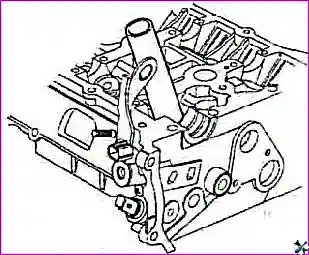
- 3. Lubricate the valve stem with engine oil. Insert the valve into the valve guide. Do not apply force when the valve stem passes through the valve stem seal. After installing the valve, check the smoothness of its movement.
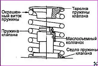
- 4. Install the valve spring so that the painted coil of the spring is located near the spring retainer (at the top), and then install the valve spring retainer.
5. Install the split collets.
a) Using a special tool (valve spring compressor and adapter), compress the valve spring and install the split collets.
Note: when compressing the valve spring, make sure that the spring retainer does not touch the valve stem seal.
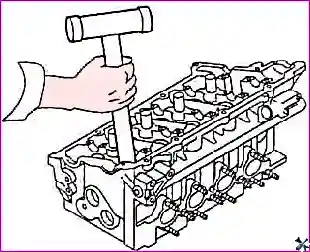
b) After removing the special tool, strike the end of the valve stem two or three times lightly with the wooden handle of a hammer and check that the split collets are securely installed.


