The fuel system uses electro-hydraulic injectors, the operation of which is controlled by an electronic control module
High pressure fuel is supplied to the injector from the rail.
A solenoid valve located at the top of the injector actuates a needle that delivers the required amount of fuel through the nozzle to each cylinder.
Multiple injection of fuel is carried out at the command of the electronic module (ECM), which controls the operation of the solenoid valves of the injectors.
The gaps in the nozzle nozzle holes are too small, and any contaminants entering them will clog the nozzle.
It is therefore important to remove dirt around all fuel system fittings before servicing it.
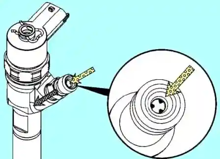
The high pressure fuel line fitting has a slotted filter that crushes small particles of dirt that have entered the fuel system.
It uses high frequency fluctuations in fuel pressure to break down most particles to a size that matches the injector bore.
All injectors are connected to a common low pressure fuel return line.
All excess fuel from the injectors, rail, fuel pump is returned to the fuel tank through the low pressure fuel line.
A low pressure check valve is installed in the low pressure line, which prevents fuel from returning to the injectors along this circuit.
The drain lines are provided on each nozzle with push-in fittings with spring-loaded clips.
If the injector is faulty or partially faulty, the engine will run erratically, consume more fuel, and there will be engine shaking.
Fuel leakage through the drain line, as a result of a malfunction of any injector, can be checked as follows:
Disconnect the fuel drain pipe from each injector
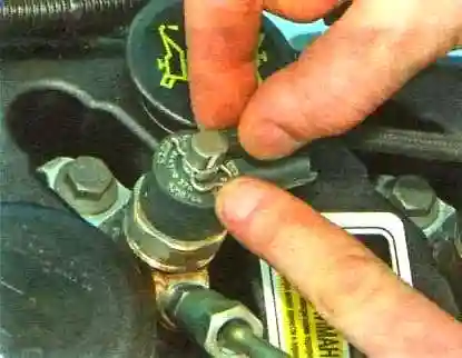
Push on the retainer for fastening the drain pipe fitting
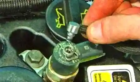
Disconnect the return line from the nozzle
We connect the separate drain hoses included in the nozzle leak test kit (catalog number 4918899).
If this kit is not available, hoses of the appropriate size can be used.
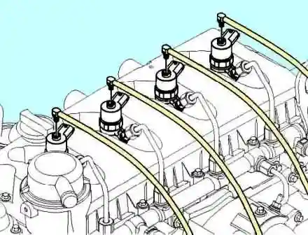
We lower all four hoses into separate measuring containers.
Start the engine and measure the amount of fuel collected per minute.
Compare the results for each injector.
Maximum fuel flow for each nozzle should be 20 ml/min.
Removing the injectors
You should not remove the nozzles without the need!
Disconnect the negative battery terminal
We clean the nozzle area with compressed air or steam.
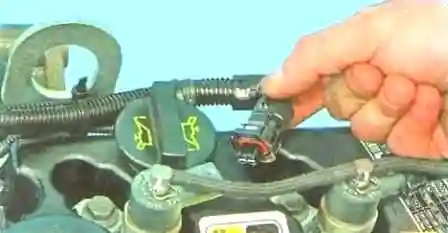
Press the latch and disconnect the wire block from the injector

Push on the latch that secures the drain pipe fitting to the nozzle

Disconnect the pipeline from the nozzle
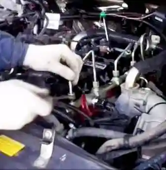
Unscrew the nut securing the high pressure pipe to the rail
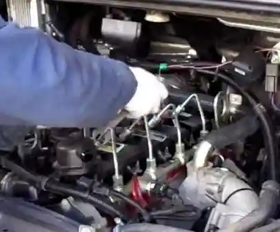
While holding the nozzle fitting from turning, unscrew the nut securing the high pressure pipe to the nozzle
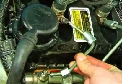
Pick up the phone
Unscrew the bolt of the injector holder and remove it
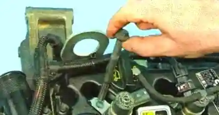
Remove the nozzle holder
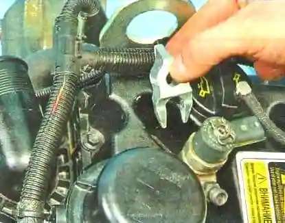
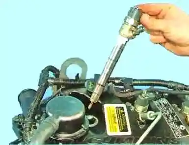
Remove the nozzle
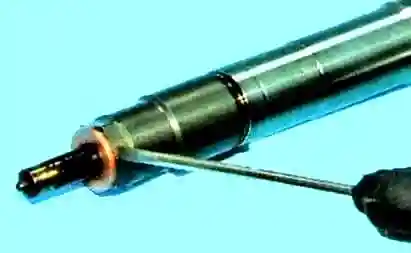
Replacing the copper sealing ring of the injector body
To remove the nozzle, we slightly move it from its place and turn the nozzle by hand, gently rocking it in different directions.
If additional force is required to remove the injector, a tool (p/n 4919661) can be used.
Carefully insert the tools into the recess in the valve cover.
In this case, you need to make sure that the two supports of the puller are located under the shoulder of the nozzle.
Using the impact slider, apply a smooth vertical force to the body.
After removing the nozzle, put a protective cover on the nozzle sprayer and mark the nozzle.
The nozzle body and nozzle should be cleaned in an ultrasonic bath using a safe, water-based detergent.
Remove the protective cover from the nozzle.
Dip the jet vertically into the ultrasonic bath.
High pressure fuel line connectors and electrical connectors must be protected from detergent.
Check the nozzle tip for carbon deposits and corrosion.
Check the electrical connector for damage.
Resistance at the contacts should be between 0.215 and 0.295 ohms.
Write down the setup code and installation location for each injector.
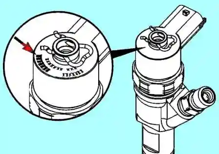
The setup code is a seven-character alphanumeric code printed on the top of the injector.
Before installing the injector, apply anti-seize compound (part number 3824879) or equivalent to those places where the injector touches the cylinder head.
When installing, we use a copper sealing washer.
The sealing washer should be 1.5±0.06 mm thick.
Only one copper sealing washer should be installed on the nozzle.
Valve cover seal should be lightly lubricated to facilitate injector installation.
Loosely tightening the fuel supply line when it is connected to the injector will facilitate accurate injector installation.
Install the clamp bolt and tighten the bolt. Tightening torque 15 Nm.
Pumping the power system and starting the engine.
Check the tightness of all connections.


