Bleeding the engine fuel system
You have to bleed the engine fuel system after replacing the fuel filters and during other work related to removing parts of the fuel system, as well as when air gets into the system
To complete the task, you will need a 12 key and a rag.
Place a piece of cloth (rag) around the fine filter.
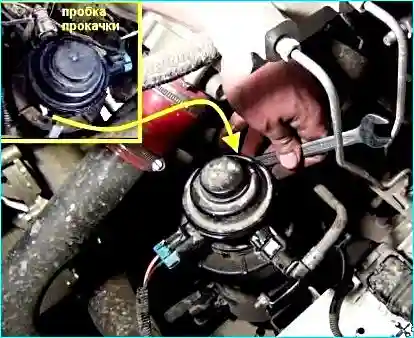
Unscrew the plug to bleed air.
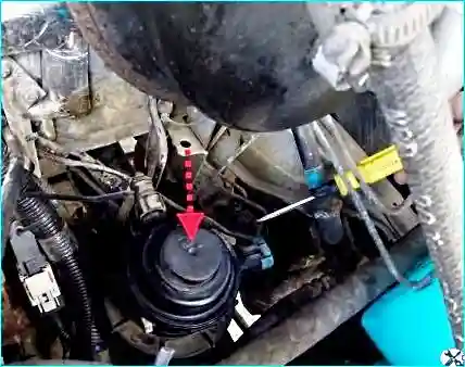
Press the manual priming pump button several times until fuel starts to come out of the hole.
Removing water from the fuel filter
The instrument cluster has a water-in-fuel warning light.
If this light does not go out after starting the engine, there is water in the fuel.
In this case, you need to stop the engine and drain the water from the fuel filter.
Place a container for draining the fuel under the drain cock.
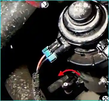
Open the drain cock by turning the wing nut counterclockwise 2 turns
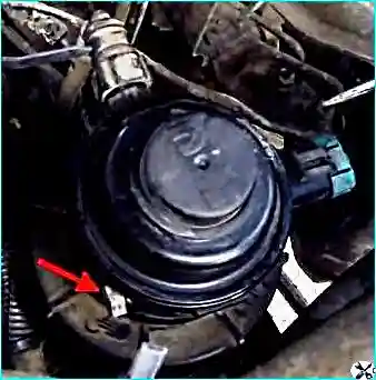
To facilitate draining, unscrew the plug on the filter housing cover
Drain the fuel from the filter along with the sediment.
After this, press the booster pump button several times until the fuel completely flows out of the filter.
Close the tap by turning it clockwise arrow.
After this, bleed the fuel system as described above.
Reinstall the bleed plug.
Checking for air in the fuel system
When replacing fuel supply lines, fuel filters, high-pressure fuel pump, high-pressure fuel lines and injectors, air gets into the fuel system.
This leads to problems when starting the engine, its uneven operation, misfires in the cylinders, loss of power and uneven fuel supply.
A few air bubbles found in the fuel line during the check are considered normal.
The appearance of many small bubbles (foam) indicates air is being sucked into the system, high resistance at the inlet, which causes cavitation, or that the system is not filled with fuel properly. If
the resistance at the fuel inlet does not exceed the norm, the source of air ingress should be identified among the following units:
- - fuel intake lines;
- - fuel lines of the complete equipment;
- - the inlet side of the fuel filters;
- - intake tubes in the fuel tanks.
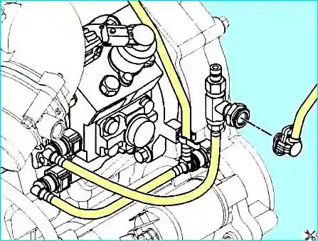
Disconnect the fuel supply line of the booster pump.
Install an adapter for a pressure gauge (No. 4918462 in the catalog) or its equivalent between the fuel supply line of the complete equipment and the fuel pump at the pump inlet.
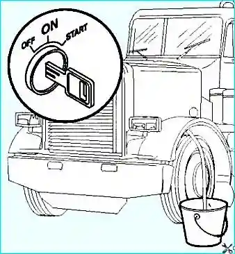
Start the engine and, several times switching from low to high speed, remove the air that got into the system when connecting the test hose.
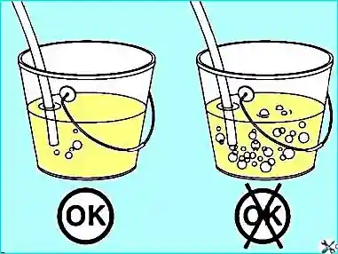
Let the engine run at idle, watching the flow of fuel coming out of the clear hose.
If air continues to bubble in the hose for several minutes, air is entering the fuel system.
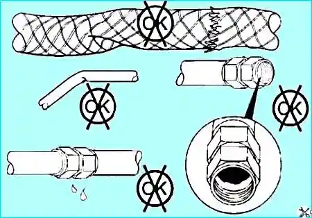
Check the fuel system for damaged fuel lines and loose connections. Replace damaged fuel lines and tighten loose connections.
Checking the resistance of the fuel return line
The resistance of the fuel return line is measured at the drain manifold located near the connection point of the drain line.
It can be found by following the fuel return lines from the point where fuel is supplied to them (pressure reducing valve common high-pressure fuel line, injector drain fittings or high-pressure pump drain channel) to the point where they are connected to another unit.
This unit will be the drain manifold.
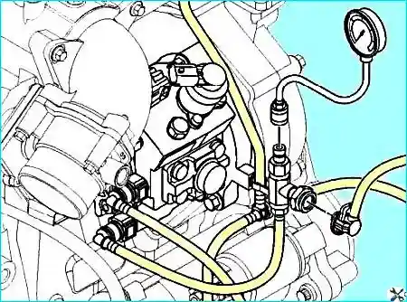
Disconnect the drain fuel line installed between the fuel pump and the manifold.
Install the adapter, catalog No. 4918462, or its equivalent, between the drain manifold and the drain fuel line.
Install the pressure gauge on the adapter fitting.
Turn on the starter, or switch the engine at low idle speed and measure the pressure.
Observe the pressure gauge readings. The maximum resistance of the drain line is 50 kPa (7.3 psi).
In case of high resistance of the fuel drain line, check the following components:
- - compliance with the standard dimensions of the fuel lines of the complete equipment going to the tank, as well as the absence of leaks, kinks and clogging in them;
- - absence of clogging in the ventilation ducts of the fuel tank.


