We remove the crankshaft and install it during the overhaul of the engine.
Preparatory Operations
- We remove the engine and install it on the stand (article - Removal and installation of the Cummins ISF2.8 GAZelle NEXT engine)
- Removing the dipstick
- Remove the dipstick tube
- Remove the oil pan
- Removing the accessory belt (article - Replacing accessory drive belt Cummins ISF2.8)
- Remove the accessory drive pulley
- Remove the cover of the front timing gears
- Removing the flywheel (article - Removing and installing engine flywheel Cummins ISF2.8)
- Remove the upper camshaft sprocket housing cover
- Remove the flywheel housing
- Remove the upper camshaft drive chain tensioner
- Remove the upper camshaft speed synchronization ring
- Remove the upper camshaft sprocket housing
- Remove the connecting rod caps
- Remove the vacuum pump
Removing the crankshaft
Remove the main bearing caps.
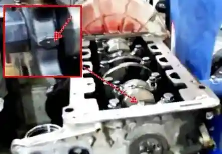
Check for alignment marks on the main bearing caps and cylinder block.
The numbering of covers starts from the front of the engine.
Remove the main bearing cap bolts, but do not remove them.
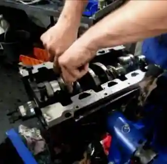
Using the 2 bolts as a lever, swing the main bearing cap and remove it. Be careful not to damage the threads of the bolts.
Remove the upper main bearing shells.
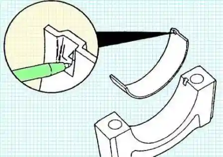
Put a relative position mark on the removed insert.
We apply marks in order to analyze the malfunction later.
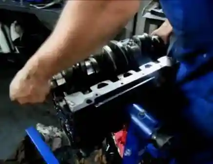
Remove the crankshaft.
The crankshaft weighs more than 23 kg. It is better to shoot with two people or with a lifting mechanism.
Cleaning the crankshaft and all parts
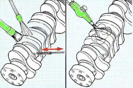
To clean the crankshaft, use hot steam or hot soapy water.
To clean the channels of the lubrication system, use a brush with a non-metal brush.
After rinsing, dry with compressed air.
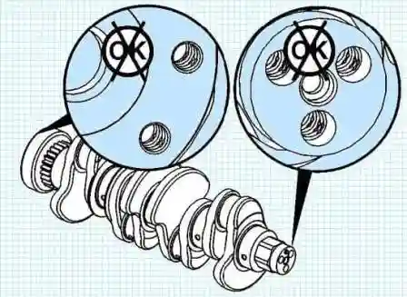
You must not clean the threads with a tap in the holes of the crankshaft.
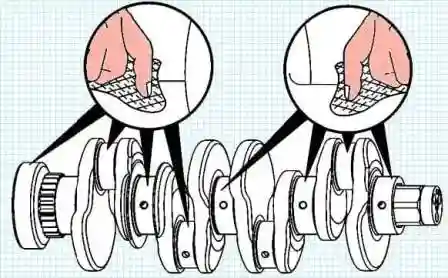
We use fine-grained sandpaper to grind the treated surfaces.
If damage is found, replace the crankshaft.
Checking the crankshaft
Check the condition of the contact zone with the front crankshaft oil seal.
Check the condition of the contact area with the crankshaft rear oil seal.
Check the condition of the connecting rod bearings.
Check the crankshaft gear for missing pitting, abrasion or missing teeth.
The rear gear of the crankshaft cannot be replaced.
If scuff marks cannot be removed with abrasive block (P/N 3823258) or equivalent, the crankshaft must be replaced.
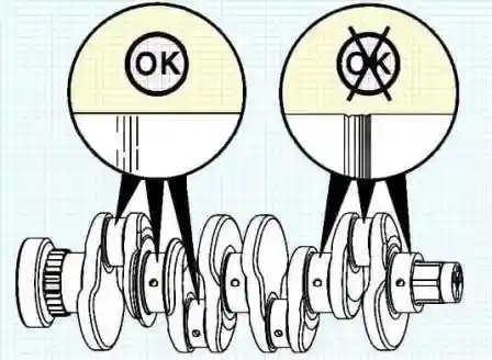
Check the journals of the main and connecting rod bearings for damage or excessive wear.
Minor scratches are acceptable.
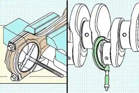
We measure the connecting rod and main journals of the crankshaft.
0.007 mm (0.0003 in.) roundness tolerance
We measure the diameter of the connecting rod journal of the crankshaft and write it down.
Standard crankshaft journal diameter 56.013 +2.323 - 58.987 -2.322 mm
We measure the diameter of the hole for the connecting rod journal of the crankshaft with the bearing installed and write it down.
Standard crankshaft journal bore diameter in connecting rod with bearing installed: 62.37 -2.456 - 62.41 +2.257 mm
The clearance in the bearing is equal to the difference between the diameter of the hole for the crankshaft in the connecting rod (with the bearing installed) and the diameter of the connecting rod journal of the crankshaft.
Clearance in connecting rod bearing 3.357 -0.132 - 3.423 +0.135 mm.
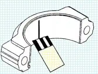
The bearing clearance can be determined using a special feeler gauge when installing the crankshaft
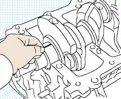
If the clearance is not correct, replace the bearing or try a different set of connecting rod bearings.
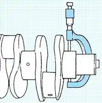
Measure the diameter of the crankshaft main journal and write it down.
Standard crankshaft journal diameter 73.987 -2.9129 mm - 74.013 +2.9139 mm
After that
We install the main bearing caps without a crankshaft with upper and lower liners.
We tighten the bolts of the main bearings in stages:
- - first stage - 50 Nm;
- - second stage - 80 Nm;
- - the third stage - rotate 90˚.
Measure the hole for the main journal with the bearing installed.
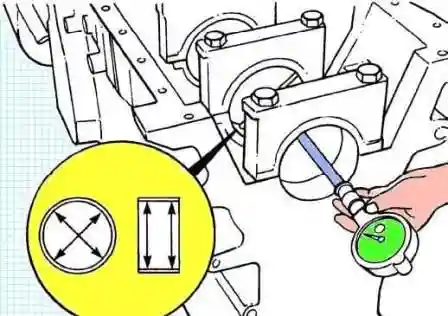
Determine the clearance in the main bearing.
The clearance in the bearing is equal to the difference between the diameter of the main journal hole (with bearing installed) and the diameter of the crankshaft main journal.
Gap should be 0.041 -0.0016 - 0.105 +0.0042 mm
Also, the clearance can be determined using a special plastic feeler gauge when assembling the engine.
Measuring the length of the main bearing bolts, for possible use in assembly.
The length of the shaft of the main bearing bolt must be no more than - 119.25 + 4.695 mm
Check the surfaces of the thrust bearing for damage or wear:
Small scratches are acceptable.
For grinding, we use fine-grained sandpaper.
The thrust bearing surfaces are located on the #4 crankshaft main journal.
Measure the allowance for the thrust bearing.
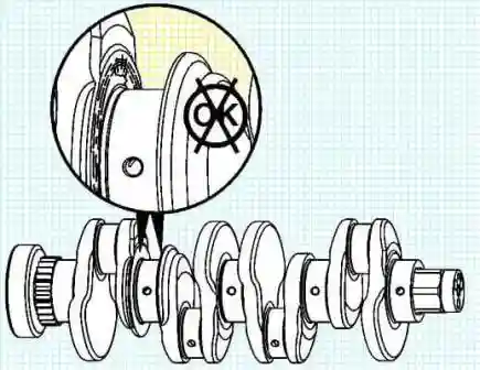
Axial distance 0.115 -0.0045 - 0.365 -0.0144 mm.
Installing the crankshaft
Lubricating the crankshaft mothorny oil.
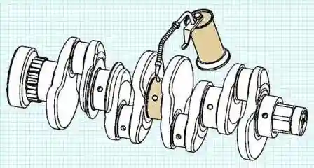
After making sure that there is no dirt and foreign particles on the back of the upper main bearing shells, insert them into the cylinder block.
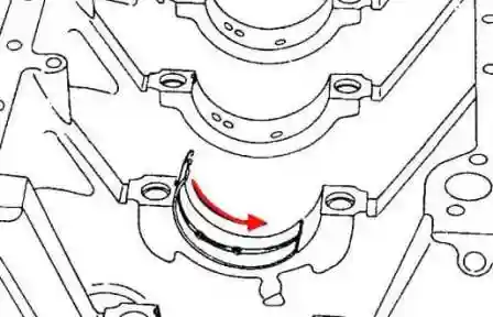
When installing, we combine the protrusions on the liners with the protrusions in the beds of the main bearings.
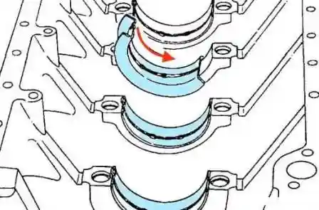
Install the crankshaft thrust bearing shell in place of the main bearing No. 4
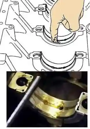
We apply engine oil to the surfaces of the main bearings and the thrust bearing from the side of the crankshaft.
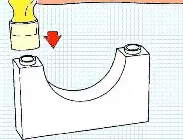
Make sure the guide bushings are in the main bearing caps.
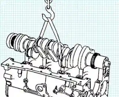
Carefully lay the crankshaft, avoiding damage to the main bearings and journals.
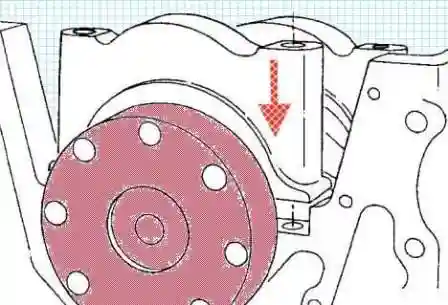
After making sure that there is no dirt and foreign particles on the back of the lower main bearing shells, insert them into the main bearing caps.
Be sure to align the tabs on the bearing shells with the tabs on the main bearing caps.
We apply engine oil to the working surface of the main bearings.
Check that the surfaces of the main bearing caps between the cap and the cylinder block are free of dirt and debris.

The main bearing caps have numbers corresponding to their installation locations, which were marked during removal.
Numbering starts from the front of the cylinder block.
The covers must be installed so that the numbers on them correspond to the numbers of the bearing beds in the cylinder block.
The tabs in the bed and the main bearing cap must be on the same side.
Install the main bearing caps.
Be sure to align the guide bushings on the main bearing cap with the corresponding holes in the cylinder block.
Lubricate the threads and lower part of the heads of the main bearing cap bolts with clean engine oil.
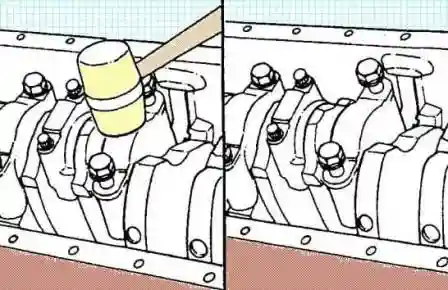
We install the main bearing caps in place by gently tapping on it with a mallet with a plastic or rubber head.
When the cover is in place, install its bolts and tighten them.
Tightening torque 50 Nm. With the final moment, we tighten the bolts after installing all the covers.
After we have installed and pre-tightened all the covers, we begin to finally tighten them:

We evenly tighten the bolts in the sequence shown in the figure.
Perform each step with all bolts before moving on to the next step.
- - first stage - 50 Nm;
- - second stage - 80 Nm;
- - third stage - rotate 90˚.
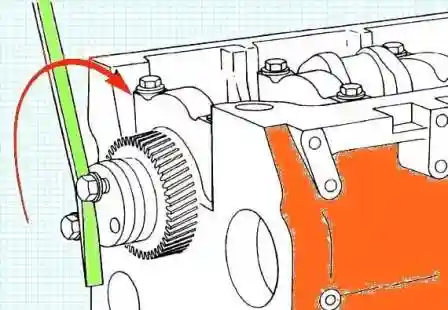
Turn the crankshaft. The crankshaft should rotate freely after installing the main bearing caps.
If the crankshaft does not rotate freely:
- - check if the crankshaft touches one of the connecting rods;
- - check the correct installation of the main bearing caps;
- - check for damage to the guide bushings or bearing surfaces of the main bearing caps during installation;
- - check the correct installation of the main bearing shells.
Measure the crankshaft end play with a dial indicator (p/n 3824564).
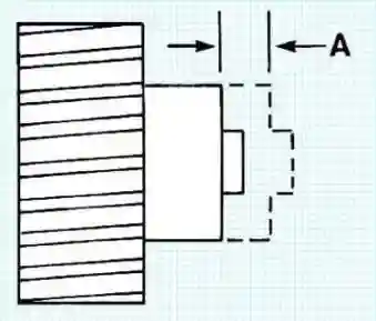
Axial play of the crankshaft 0.023 -0.0009 - 0.365 +0.0144 mm.
If the axial play is not correct:
- - if the axial play of the crankshaft is below normal, check that there are no obstacles restricting its movement (oil pump, connecting rod, etc.);
- - if the crankshaft axial play is higher than normal, check the surface of the crankshaft thrust bearing. In addition, check that the thrust bearing is installed correctly.
After that, we assemble all the parts in accordance with the assembly technology.


