


The hub is fitted with a double-row roller bearing that requires no adjustment or additional lubrication during operation.
When the hub is pressed out of the bearing, the bearing is destroyed. Therefore, it should only be removed for replacement.
Required tools:
- — Open-end, ring, and socket spanners (15 mm and 24 mm);
- — Torque wrench;
- — Allen key (6 mm);
- — Hammer and a set of drifts;
- — Wheel brace for the wheel nuts.
Important: The bearings must be replaced simultaneously on both front wheel hubs.
Prepare the vehicle for the task and place wheel chocks under the rear wheels.

Raise the front of the vehicle and remove the corresponding wheel.

Loosen the six bolts securing the brake disc.
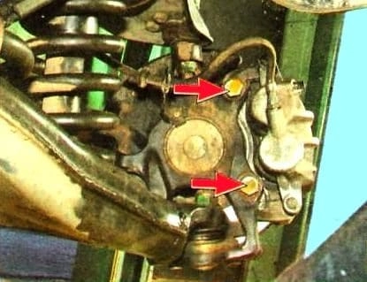
Unscrew the two bolts securing the front brake mechanism caliper.
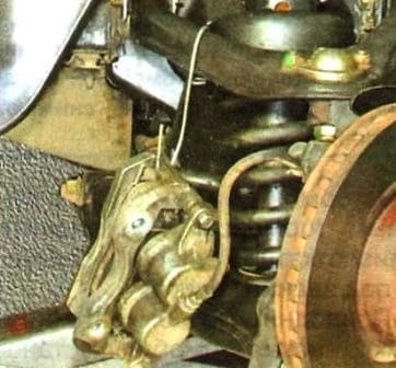
Remove the caliper and securely tie it to the suspension components with wire or a special hook, absolutely avoiding letting it hang by the brake hose.

Using an Allen key, unscrew the five bolts securing the bearing housing to the steering knuckle.
Attention: These bolts are tightened to a high torque and secured with anaerobic thread locker. Therefore, use only high-quality tools. It is recommended to gently tap these bolts with a hammer beforehand to break the layer of thread locker. If the key slips in the bolt head, it will be extremely difficult to remove.

Remove the hub with the brake disc assembly.


Unscrew the bolts securing the brake disc to the hub and remove the disc.

Unscrew the clamping bolt «А» and remove the pressure ring «Б» (on vehicles with ABS, this is the wheel speed sensor target disc).
Press the hub out of the inner ring of the bearing using a drift. If the outer part of the bearing's inner ring remains on the hub, press it off using a special puller.

Press the hub into the new bearing using a press and a drift until it bottoms out, applying force only to the inner ring of the bearing.
Important: Do not hammer the hub into the bearing, as it may be destroyed.
Install the pressure ring (or ABS target disc) and tighten the clamping bolt to a torque of 280–320 N·m. While tightening the bolt, rotate the hub relative to the bearing to ensure even seating.
Before screwing in the bolt, clean off the old sealant and degrease its threaded part and the hole in the hub. Apply anaerobic thread locker to the thread.
Install the brake disc onto the hub.

Before installing the brake disc, thoroughly clean the rust and scale from the mating surfaces of the hub.

Also clean the rust and scale from the disc itself. Even the tiniest particle of dirt trapped between the mating surfaces will cause disc runout and vibrations during braking.
Install the hub assembly in the reverse order.

Before screwing in the bolts securing the bearing housing to the steering knuckle, clean off the old sealant and degrease the threaded part of the bolts and the holes in the steering knuckle.
Apply anaerobic thread locker to the threaded part of the bolts.
Tighten the bolts to a torque of 52–59 N·m.