


Prepare the vehicle for the work.
Disconnect the negative terminal of the battery.
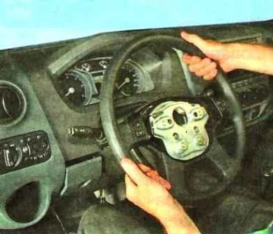
Set the steering wheel to the straight-ahead driving position.
Remove the steering wheel (see article – Removal of the steering wheel and steering column cover).
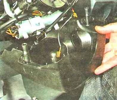
Remove the upper and lower parts of the steering column cover.
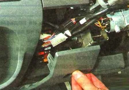
Carefully remove the lower decorative shield of the instrument panel, overcoming the resistance of the spring clips.
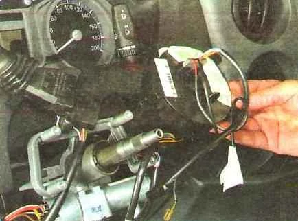
Disconnect and remove the switch block under the steering wheel as an assembly (see article – Replacement of switches under the steering wheel).
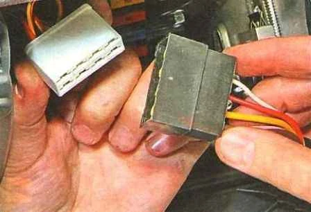
Disconnect the electrical connector of the ignition lock.
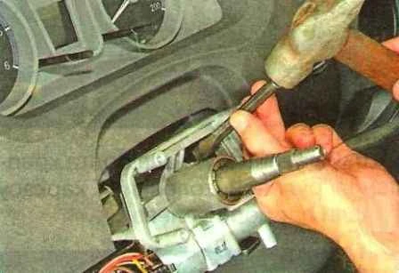
If the steering column is being removed for repair or replacement, dismantle the ignition lock from it by unscrewing the two mounting bolts.
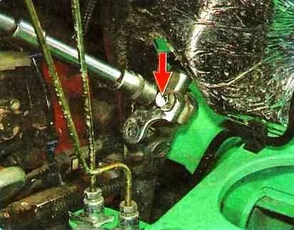
In the engine compartment, unscrew the clamping bolt connecting the upper and lower intermediate shafts.
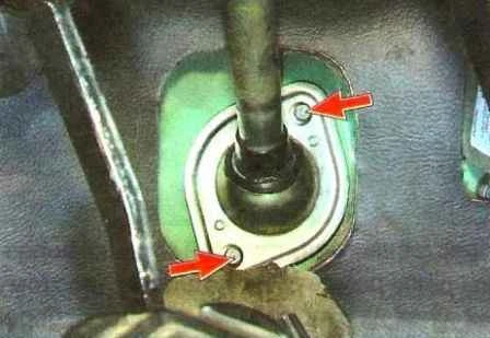
From inside the cabin, under the instrument panel, unscrew the two bolts of the ball joint support of the upper intermediate shaft.
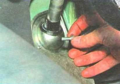
Completely remove the mounting bolts.
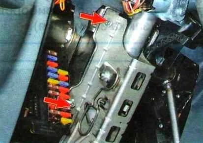
Unscrew the two bolts securing the steering column to the instrument panel frame on the left side.
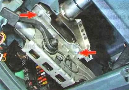
Similarly, unscrew the two mounting bolts on the right side.
Remove the steering column assembly from the vehicle.

Note: Installation is performed in the reverse order of removal.
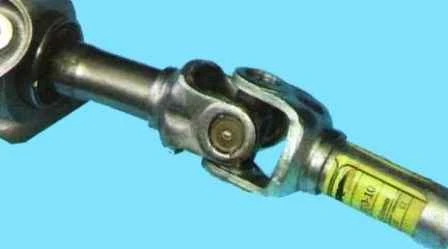
Important: The universal joints (crosses) of the steering column shaft are non-disassembleable and cannot be repaired. If there is play or sticking, the shaft must be replaced as a complete unit.
Material recommendation: Before final tightening, apply anaerobic thread locker (e.g., Loctite 243 or equivalent) to the threaded part of the four steering column mounting bolts and the two intermediate shaft support bolts.
Tightening torques for threaded connections:
- — Steering column mounting bolts to the frame: 18–25 N·m;
- — Intermediate shaft support mounting bolts: 5.5–8.0 N·m;
- — Clamping bolt of the intermediate shafts' clamp connection: 28–32 N·m.