Checking and setting No. 1 cylinder to TDC Cummins ISF2.8 (GAZelle NEXT)
Checking and setting No. 1 cylinder to TDC on the compression stroke is required when carrying out work to remove the camshaft drive chain.
It must be borne in mind that when setting by the marks on the crankshaft pulley and the oil pump housing, either the No. 1 cylinder piston or the No. 4 cylinder piston may be in this position.
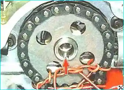
There are no marks on the camshaft sprocket. There is only a slot on the front end of the camshaft, from which it can be determined that the camshaft is also at TDC.
To determine which of the cylinders is on the compression stroke, the cylinder head cover must be removed and the ease of movement of the valve rockers of the first and fourth cylinders checked, or the phase sensor trigger wheel removed so as to determine it from the position of the slot on the rear end of the camshaft.
After this, the coincidence of the marks on the crankshaft pulley and the oil pump housing must be confirmed.
If the marks do not coincide, the valve timing setting has been disturbed.
In this case the camshaft sprocket securing bolt must be slackened and, with the camshaft held stationary, the crankshaft turned until the marks coincide.
Tools and materials required
To carry out the work you will need: a pin about 6 mm in diameter to lock the crankshaft, a large screwdriver for turning the flywheel, a camshaft locking tool, a 10 mm socket and a torque wrench.
Materials and parts used:
- New timing case cover gasket — when removing the cover.
- New cylinder head cover gasket — when removing the cover (if necessary).
- Rags, cleaner for removing contamination from the pulley, oil pump housing and camshaft surfaces.
Important: when setting by the marks on the crankshaft pulley and the oil pump housing, either the No. 1 or the No. 4 cylinder piston may be in this position. To determine the compression stroke accurately, the rockers or the position of the slot on the rear end of the camshaft must be checked.
Checking the coincidence of the marks
We turn the engine crankshaft until the marks on the crankshaft pulley and the oil pump housing coincide.
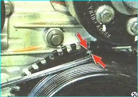
We lock this crankshaft position by inserting a pin about 6 mm in diameter into the hole.
The crankshaft can be turned by the flywheel ring gear. To do this we extract the plug from the hole in the flywheel housing.
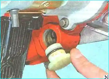
We turn the flywheel by the ring gear teeth with a large screwdriver, resting it on the edge of the hole.
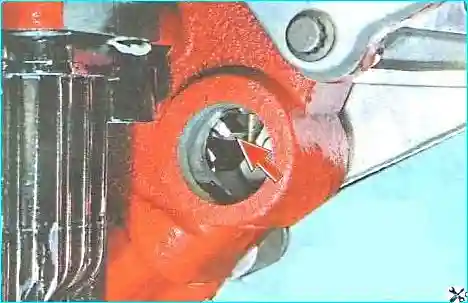
We remove the vacuum pump.
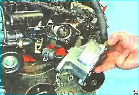
We check the position of the slot on the front end of the camshaft for the vacuum pump shaft nose.
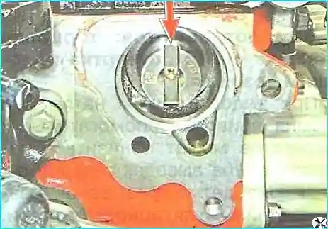
The slot must be positioned strictly vertically.
Determining the cylinder on the compression stroke
To determine in which cylinder the piston is at TDC on the compression stroke, we remove the head cover.
We try to rock by hand on their shafts the rocker “A” of the valve drive of the first cylinder and the rocker “B” of the valve drive of the fourth cylinder.
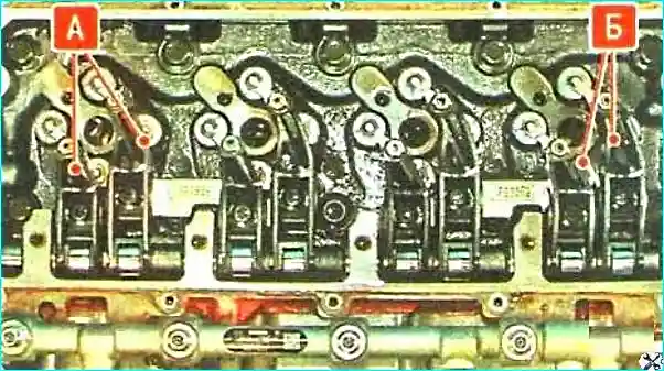
In the cylinder whose two rockers move freely, the piston is at TDC on the compression stroke.
To restore the correct valve timing, the engine must be removed, since access to the timing drive on the vehicle is impossible.
Restoring the valve timing on the removed engine
On the removed engine, to set the valve timing correctly, we extract the locking pin that had been inserted through the holes in the crankshaft pulley and the oil pump housing.
We turn the crankshaft in the required direction until the slot on the front end of the camshaft reaches the correct position.
We lock the camshaft in this position with a tool.
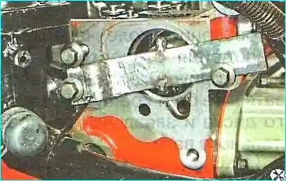

We unscrew the five bolts securing the timing case cover.
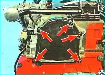
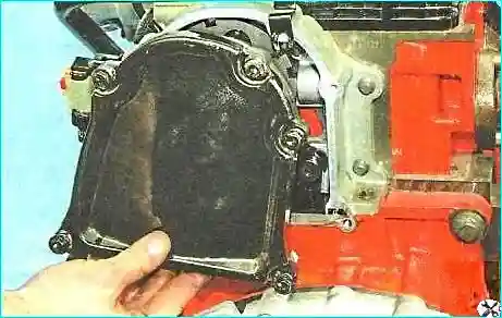
We remove the cover.
While holding the camshaft from turning by the holes in the phase sensor trigger wheel, we slacken the bolt securing the trigger wheel and the camshaft sprocket.
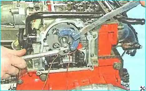
We turn the crankshaft until the holes in its pulley and in the oil pump housing coincide, and tighten the bolt securing the trigger wheel and the camshaft sprocket.
Determining TDC without removing the cylinder head cover
If, on the removed engine, it is necessary to determine which cylinder is at TDC on the compression stroke, this can be done without removing the cylinder head cover.
We fully unscrew the bolt securing the phase sensor trigger wheel.
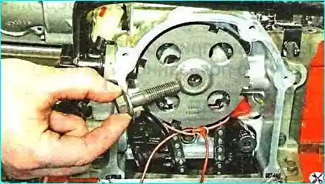
We remove the wheel.
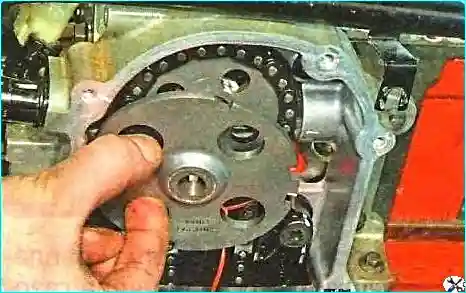
After the wheel is removed, the slot on the rear end of the camshaft becomes visible; it will point strictly downwards if the No. 1 cylinder piston is at TDC on the compression stroke.