Replace the hub bearing when play appears.
Bearing wear can be identified by increased noise when driving.
Operations for replacing a hub bearing with and without ABS are similar.
The only difference is the installed speed sensor in the steering knuckle.
Preparing the car for work.
We install the car on a viewing hole or a lift.
In order to unscrew the hub nut, place stops under the wheels.
Usually, the hub nut is tightened with great force, so you need an assistant to apply the brake while unscrewing the nut.
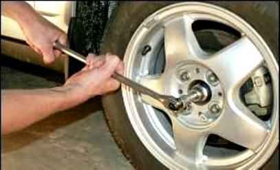
With a head of 30 (Fig. 1), unscrew the wheel bearing nut.
Hang out and remove the wheel.
Remove the front wheel speed sensor (if installed).
Remove the brake disc.
Using a Torx T-30 wrench, unscrew the three screws securing the brake shield to the steering knuckle and remove the shield.
Disconnect the tie rod end from the steering knuckle
Remove the ball joint pin from the steering knuckle hole
Disconnect the shock absorber from the steering knuckle
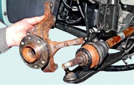
Remove the steering knuckle (Figure 2) assembly with the hub from the splined shank of the wheel drive outer hinge housing.
When removing the steering knuckle from the drive, try not to pull the drive shaft out of the CV joint or gearbox.
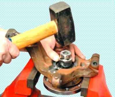
Let the steering knuckle rest on the vise jaws (Figure 3).
By striking the end of the hub through a mandrel or head of the appropriate size
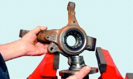
Press out the hub.
In this case, the inner race of the bearing, located closer to the hub flange, remains on the hub.
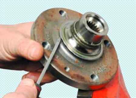
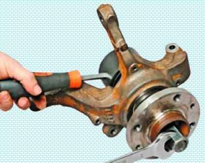
Use a screwdriver to pry off the protective washer that covers the bearing seal
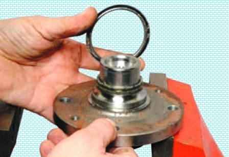
Remove the washer
We clamp the hub flange in a vice
Insert a chisel between the ends of the inner ring of the bearing and the shoulder of the hub.
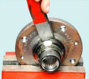
By striking the chisel with a hammer, we move the inner ring of the bearing along the hub.
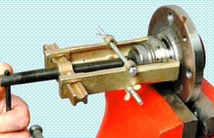
Then, in the resulting gap, we insert the grips of the puller and finally press the inner ring of the bearing from the hub.
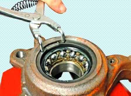
Using circlip pliers, remove the bearing circlip from the knuckle groove.
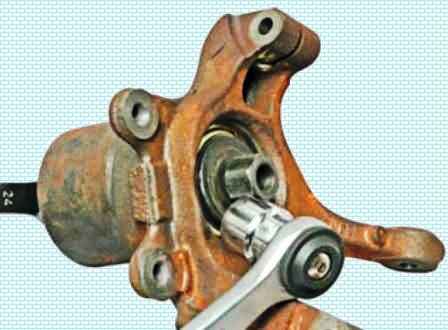
Cup remove com press the bearing out of the steering knuckle.
The bearing can also be punched out. to do this, we rest our fist on the vise jaws.
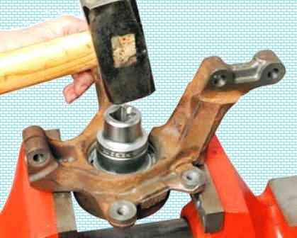
By striking the end of the outer ring of the bearing through a mandrel or head of a suitable size, we press the bearing out of the knuckle.
Before installing a new bearing, we clean the mounting hole in the steering knuckle and the groove for the retaining ring.
Using a file, we clean the nicks from the chisel on the hub.
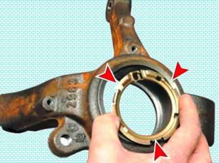
Before pressing the bearing, we put the adjusting ring of the wheel speed sensor into the hole of the steering knuckle (with the tabs centering the ring - inside the fist).
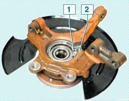
Orient the ring in the knuckle hole so that the speed sensor holder on the ring 1 (Figure 13) is located in the knuckle groove 2 (shown on the assembled hub assembly for clarity).
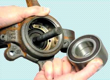
After installing the cup puller screw with the support washer, insert a new bearing into the knuckle hole.
On a vehicle with ABS, the bearing should be installed so that its dark-colored protective washer (made of magnetic material) faces the wheel speed sensor mounting ring.
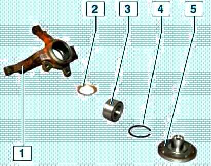
Figure 15 shows the details of the hub assembly.
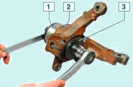
We press the bearing, applying force through the puller cup to the end of the outer ring of the bearing, while the puller washer should rest on the steering knuckle (Figure 16).
After pressing the bearing, we install a retaining ring in the groove of the fist.
Then we press the hub into the bearing.
When pressing the hub, the puller cup must rest on the end face of the bearing inner ring (Figure 17).
Further assembly and installation of the hub assembly is carried out in the reverse order.
The fasteners listed below must be replaced:
- - front wheel hub nut;
- - nut of the front suspension arm ball joint bolt;
- - nuts of the bolts of the steering knuckle to the front suspension strut.
Install the ball joint bolt of the lower arm of the front suspension to the steering knuckle with the head towards the front of the vehicle.
Install the spline shank of the front wheel drive shaft into the front wheel hub.
Install the steering knuckle on the front suspension strut, insert the mounting bolts and tighten, without tightening, new nuts (wrench 18, interchangeable head 18, ratchet wrench).
Install the ball joint pin of the front suspension arm into the steering knuckle, install the mounting bolt and tighten the new nut.
Nut tightening torque 62 Nm (6.2 kgf.m) (wrench 16, interchangeable head 16, ratchet wrench, torque wrench).
Tighten the nuts of the bolts securing the steering knuckle to the front suspension strut.
Monut tightening torque 105 Nm (10.5 kgf.m) (wrench 18, interchangeable head 18, torque wrench)
Connect the tie rod end to the knuckle arm.
- - install front brake disc cover;
- - install front brake disc.
Install a stop on the front wheel hub and secure it with two wheel bolts.
Tighten the new front wheel hub nut and remove the stop.
Nut tightening torque 280 Nm (28.0 kgf.m) (replaceable head 17, interchangeable head 32, knob, torque wrench).
- - set the front wheel speed sensor;
- - install front brake assembly.
Install the front wheel.
Depress the brake pedal 2-3 times to set the pistons of the wheel brake cylinders to the working position.
Check and, if necessary, adjust the alignment of the front wheels.


