On-board DC vehicle network with a nominal voltage of 12 V
Electrical equipment is made according to a single-wire circuit: the negative terminals of sources and consumers of electricity are connected to the "ground" - the body and power unit of the car, which act as a second wire.
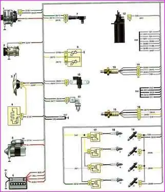
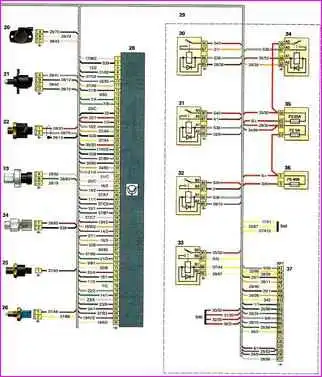
Scheme is divided into two parts. Each scheme corresponds to the numbering of the parts included in the scheme.
Notations on the diagram: 1 - generator; 2 - air conditioner compressor; 3 - cooling system fan; 4 - additional resistor; 5 - starter; 6 - battery; 7 - absolute air pressure sensor; 9 - coolant temperature sensor; 10 - crankshaft position sensor; 11 - intake air temperature sensor; 12 - adsorber purge valve; 13 - control oxygen concentration sensor; 14 - block connection with the wiring harness of the control oxygen concentration sensor; 15 - diagnostic oxygen concentration sensor; 16 - block connection with the wiring harness of the diagnostic oxygen concentration sensor; 17 - ignition coils;
Wiring diagram continued for mechanical damper motor
18 - spark plugs; 19 - nozzles; 20 - throttle position sensor; 21 - idle speed regulator; 22 - knock sensor; 23 - refrigerant pressure sensor; 24 - pressure sensor in the power steering system; 25 - insufficient oil pressure sensor; 26 - reverse light switch; 28 - electronic engine control unit (controller); 29 - fuse box and relay in the engine compartment; 30 - high speed relay of the cooling fan; 31 - low speed relay for the cooling system fan; 32 - air conditioner compressor relay; 33 - relay of the fuel pump and ignition coils; 34 - main relay; 35, 36 - fuses in the relay and fuse box in the engine compartment; 37- block connection with body wiring harness
A diagram of the rear of the body wiring harness is located in the article - Nissan Almera Body Rear Wiring Diagram


