We remove the driven and driving disk when replacing, as well as when replacing the rear crankshaft oil seal and when replacing the flywheel
If you need to replace clutch parts, the gearbox can not be completely removed from the car, but slightly moved away from the engine to the desired distance.
We install the car on a lift or an inspection ditch and disconnect the negative battery terminal
Remove the left wheel drive (see the article - How to remove the wheel drive)
We unscrew the bolt securing the left subframe bracket to the body and loosen the nut that secures the bracket to the suspension arm (see the article - Removing the arm)
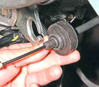
Disconnect the clutch cable from the clutch release mechanism fork and the bracket on the gearbox (see the article - Replacing the clutch cable)
Disconnect the gearbox control rod from the switch on the gearbox (see article - Repair of the shift mechanism)
Disconnect the wiring harness connector from the plug connector of the hole in the gearbox for the vehicle speed sensor
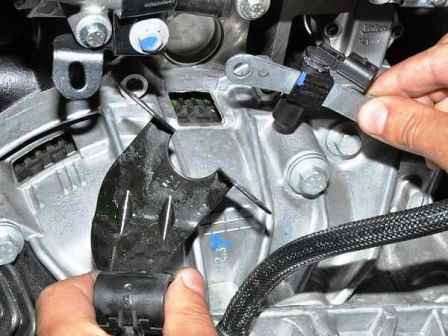
Remove the crankshaft position sensor (see the article - Removing the elements of the car's CUD)
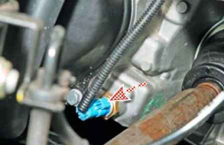
Disconnect the wiring harness from the reverse light switch
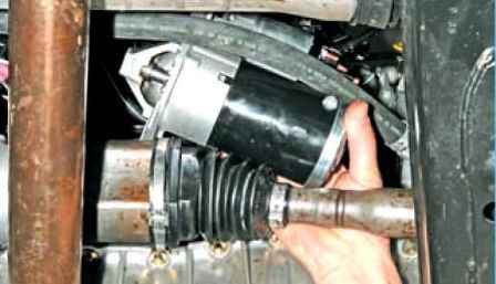
We remove the starter (see the article Removing and checking the starter)
Remove the breather hose from the gearbox housing fitting.
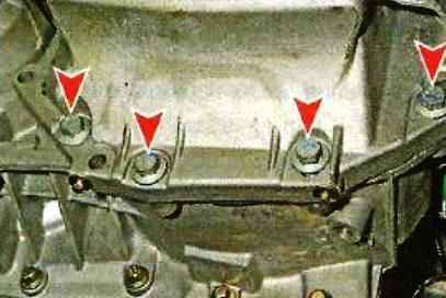
We unscrew the four bolts securing the engine oil pan to the gearbox
We substitute adjustable stops under the engine and gearbox.
Remove the rear and left supports of the power unit (article - Replacing the supports of the power plant)
Disconnect the ground wires from the gearbox, unscrew the bolts and nuts securing the gearbox to the engine block (article - Removing the Nissan Almera gearbox)
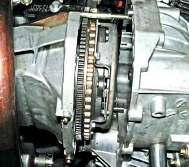
Holding the body of the inner hinge of the right wheel drive, we remove the gearbox from the engine, removing the input shaft from the hub of the clutch disc.
In this case, the splined shaft of the side gear of the differential will come out of the tip of the housing of the inner joint of the right wheel drive.
We take the gearbox away from the engine to a distance at which it will be possible to remove the clutch parts, and rest the left side of the gearbox on the subframe.
To replace the release bearing, we move it along the guide sleeve to the end of the gearbox input shaft, disengaging the legs of the clutch release fork from engagement with the bearing clutch
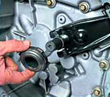
Remove the bearing (shown on the removed gearbox)
Remove the fork from the ball joint and remove the end of the fork from the dirt cover.
Before installing the bearing, we apply Litol on the surface of the guide bushing, the paws of the clutch release fork, and also on the ball bearing of the fork.
We replace the torn rubber boot of the clutch release fork with a new one.
Install the clutch release bearing in reverse order
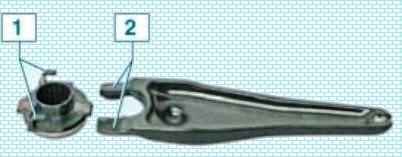
When installing the foot bearing, 2 forks must enter the plastic hooks 1 of the bearing sleeve
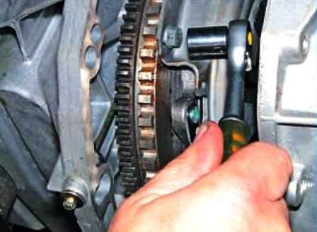
To remove the clutch discs, we install a mounting spatula between the teeth of the flywheel crown and, leaning on the gearbox mounting pin, unscrew the six bolts securing the basket to the flywheel with a head of 11.
We unscrew the bolts evenly, each no more than one turn per pass, so as not to deform the clutch basket.
If the bolts are difficult to unscrew, then you need to tap the bolt heads with a soft-faced hammer.
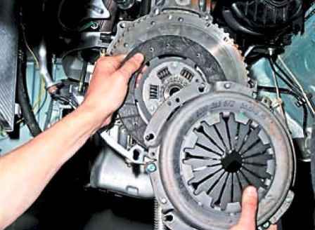
Remove the basket and the clutch disc (shown with the gearbox removed)
Install the slave and master disk in reverse order.

When installing the driven disk, orient its protruding part to the clutch basket.
Insert the clutch basket so that the pins fit into the corresponding holes in the basket
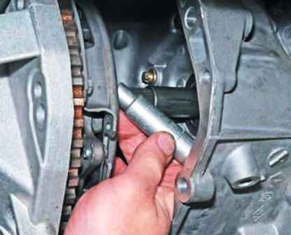
We insert the centering mandrel into the splines of the driven disk and insert the mandrel shank into the hole of the crankshaft flange.
The mandrel is suitable for clutching VAZ cars.
We bait and evenly tighten the oppositely lying bolts of the clutch cover to the flywheel one turn per pass.
Finally tighten the bolts to 20 Nm.
We take out the centering mandrel of the driven disk.
Install the gearbox and all removed parts in the reverse order and adjust the clutch drive.


