


General information about the К9К engine
Some models of the Renault Megane 2 are equipped with К9К diesel engines of 86 hp. The K9K TURBO engine is turbocharged, in-line, liquid-cooled, with four cylinders, with an OHС valve train, and is located transversely in the engine bay.
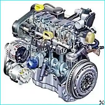
Engine characteristics:
- compression ratio — 18.25;
- cylinder bore — 76 mm;
- piston stroke — 80.5 mm;
- engine displacement — 1461 cm³.
Construction of the cylinder block and head
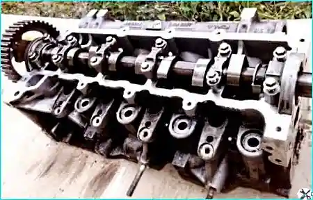
Design features:
- The cylinder head is made of aluminium alloy.
- The cylinder head gasket is made of metal, thanks to which it is more resistant to high temperature and pressure.
- The cylinder block is cast of grey iron with already formed cylinder liners.
Crankshaft and connecting rod and piston assembly
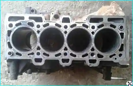
Crankshaft:
- The crankshaft bearings have cast-iron caps forming part of the block, including the bolts.
- In both halves of the bearings are inserted shells with tab locks and lubricating grooves.
- The axial movement of the crankshaft is limited by two half-rings installed in the grooves of the seat of the middle main bearing.
- The oil channels to the bearings are made transversely (diagonally).
- The flywheel, cast of iron, is installed on the rear end of the crankshaft and secured by six bolts.
Connecting rod and piston assembly:
- The pistons are made of aluminium castings with a graphite coating of the skirt to reduce friction.
- In the piston crown there is a recess with a guide rib to ensure turbulent air movement.
- The piston pins are press-fitted with an interference fit into the upper ends of the connecting rods.
- The connecting rods are steel, forged, with an I-section shank. The cap and the connecting rod are machined as a single unit — fitting the cap to another connecting rod is inadmissible.
Lubrication system
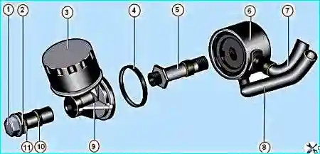
1 — oil filter bracket securing bolt; 2,10,11 — sealing rings; 3 — oil filter;
4 — heat exchanger sealing ring; 5 — heat exchanger securing bolt; 6 — heat exchanger;
7,8 — oil pipelines; 9 — oil filter bracket
Features of the lubrication system:
- The oil pump with an excess pressure valve is driven by a roller chain from the crankshaft sprocket.
- Under the crankshaft there is an oil deflector.
- The engine sump of aluminium alloy is combined with the front and rear covers.
- The oil heat exchanger (6) and the oil filter (3) are integrated into the lubrication system.
- The oil filter is provided with a replaceable paper filter element.
Cooling system
Features of the cooling system:
- The cooling system is sealed, with an expansion tank.
- Forced circulation is provided by a centrifugal water pump driven from the crankshaft by the auxiliary drive belt.
- The thermostat closes the large circuit of the system when the engine is not warmed up.
Turbocharging and exhaust gas recirculation system
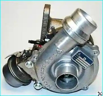
Turbocharging:
- The exhaust manifold is attached to the turbocharger flange by nuts.
- Lubrication of the turbine bearings is included in the general engine lubrication system.
- The turbocharging system is complemented by an exhaust gas recirculation system.
- The quantity of gases supplied is regulated by an electromagnetic recirculation valve.
Fuel system and glow plugs
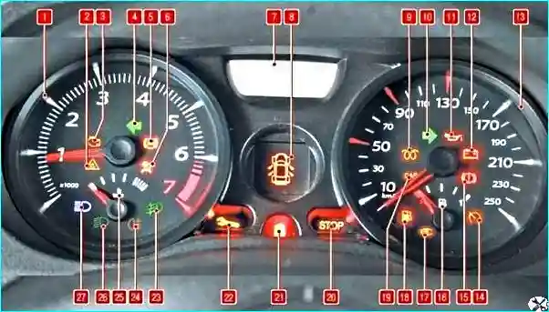
Operating principle of the diesel engine:
- Pure air is drawn into the cylinders. During compression the pressure and temperature rise sharply (to 700–900 °C).
- Before TDC diesel fuel is injected into the cylinder, which self-ignites.
- For cold starting glow plugs are installed in the combustion chamber, which heat up before the starter is switched on.
- After the plugs have heated up the indicator in the instrument cluster goes out and the engine can be started.
Fuel system:
- The injection pump is driven by the toothed belt from the crankshaft pulley.
- An electromagnetic valve is installed in the injection pump — to stop the engine the voltage supply is interrupted, the valve closes the fuel channel.
- The fuel before the injection pump passes through the fuel filter for cleaning from contaminants and water.
Tightening torques of the parts of the К9К engine
Important! All tightening torques are indicated in daN·m (decanewton-metres). 1 daN·m ≈ 10 N·m.
| Part | Tightening torque |
|---|---|
| Cylinder head securing bolts | According to the scheme 2.5 daN·m, then tighten by 255° ± 10° |
| Bolts securing the camshaft bearing caps | 1 daN·m |
| Bolt securing the camshaft toothed pulley | 3 daN·m + 84° |
| Bolts securing the vacuum pump | 2.1 daN·m |
| Bolts securing the thermostat housing | 1 daN·m |
| Nuts of the exhaust manifold securing studs | 2.6 daN·m |
| Bolts securing the exhaust gas recirculation valve | 2.1 daN·m |
| Glow plugs | 1.5 daN·m |
| Bolts securing the injection pump | 2.1 daN·m |
| Bolt securing the injector flange | 2.8 daN·m |
| Bolts securing the fuel rail | 2.8 daN·m |
| High-pressure fuel pipe union | 3.8 daN·m |
| Bolts securing the cylinder head cover | 1 daN·m |
| Bolt securing the timing drive tensioner roller | 2.5 daN·m |
| Bolts securing the crankshaft main bearing caps | 2.7 daN·m + 47° ± 5° |
| Nuts of the connecting rod cap bolts | 2 daN·m + 45° ± 6° |
| Bolts securing the oil pump | 2.5 daN·m |
| Bolts securing the water pump | 1.1 daN·m |
| Bolts securing the flywheel | 5–5.5 daN·m |
| Bolt securing the crankshaft pulley | 2 daN·m + 130° ± 15° |
| Bolts securing the alternator | 2.1 daN·m |
| Air conditioning compressor bolts | 2.1 daN·m |
Note: for the bolts securing the oil sump and some other connections, the description of the procedure should be consulted in the corresponding sections of the manual.


