


The vehicle is equipped with two diagonally split brake circuits.
One circuit operates the front right and rear left wheels, the other operates the front left and rear right wheels.
When only one circuit is working, the brake pedal must be pressed harder to stop the vehicle.
The pedal travel increases and the braking distance lengthens.
When the brake pedal is pressed, the pushrod acts on the two pistons of the master cylinder, which, via the brake booster, generate pressure in the system.
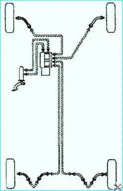
Fig. 1. Brake actuation diagram with diagonal split
The master cylinder is not repairable. If it fails, it must be replaced as a complete assembly.
The pistons transmit the pedal force via the hydraulic lines to the brake calipers.
The caliper pushes the piston of the wheel cylinder, which in turn presses the brake pads against the brake disc.
When the pedal is released, the piston returns to its original position and the pads move away from the disc.
The distance between the pads and the disc is 1 mm, which is sufficient for the disc to rotate freely.
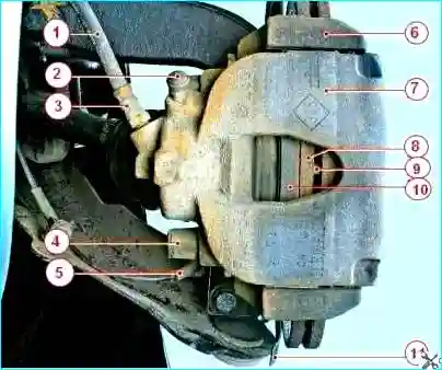
Fig. 2. Front wheel brake: 1 — flexible brake hose; 2 — protective cap of the bleed valve; 3 — flexible brake hose fitting; 4 — dust cover of the lower guide pin; 5 — wheel speed sensor; 6 — pad carrier; 7 — floating caliper; 8 — brake disc; 9 — bridge of the disc cooling air channels; 10 — inner brake pad; 11 — brake shield
The front brakes (Fig. 2) are disc brakes with automatic pad-to-disc clearance adjustment, featuring a floating caliper 7.
A single-piston wheel cylinder is mounted on the floating caliper.
The pad carrier 6 is bolted to the steering knuckle.
The floating caliper is secured by guide pins inserted into the holes of the pad carrier.
The guide pins are lubricated with grease and protected by dust boots.
A piston with a sealing ring is installed in the wheel cylinder bore.
The elasticity of this ring maintains the optimum clearance between the pads and the ventilated disc, the surface of which is protected by a brake shield.
During braking, the piston, under hydraulic pressure, presses the inner pad against the disc; by reaction, the floating caliper moves on the pins and the outer pad is also pressed against the disc, with equal clamping force.
When the brakes are released, the piston, due to the elasticity of the sealing ring, retracts from the pad, creating a small clearance between the pads and the disc.
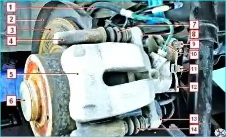
Fig. 3. Rear wheel brake: 1 — flexible brake hose; 2 — brake shield; 3 — brake disc; 4 — pad carrier; 5 — floating caliper; 6 — protective cap of the hub nut; 7 — dust cover of the upper guide pin; 8 — upper guide pin bolt; 9 — parking brake cable end; 10 — brake line; 11 — protective cap of the bleed valve; 12 — parking brake actuating lever; 13 — lower guide pin bolt; 14 — dust cover of the lower guide pin
The rear brakes are disc brakes with automatic adjustment.
The brake pads are actuated by a single hydraulic wheel cylinder.
The optimum clearance between the disc 3 (Fig. 3) and the pads is maintained in the same way as for the front brakes.
The parking brake cable end 9 is connected to the actuating lever 12, mounted on the floating caliper 5.
The parking brake lever, located between the front seats on the floor tunnel, is equipped with a cable tension adjustment mechanism and is connected to the equaliser by the front cable.
The front cable ends are connected to the tension mechanism equaliser.
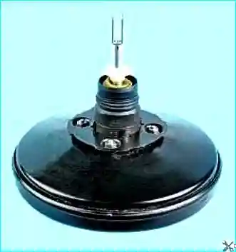
Fig. 4. The vacuum brake booster reduces the pedal effort, making driving easier
The vacuum booster uses a diaphragm, with a vacuum created on both sides during normal operation.
During braking, air is admitted to one side of the diaphragm, creating atmospheric pressure.
The pressure difference transmitted through the diaphragm moves the pushrod towards the vacuum, providing braking assistance.
When the brake pedal is released, air is drawn from the booster chamber through the control valve, restoring the vacuum.
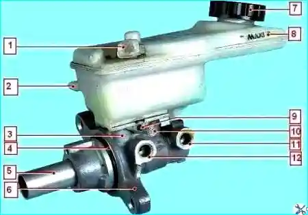
Fig. 5. Master cylinder with reservoir: 1 — brake fluid level sensor connector; 2 — fluid outlet fitting to the clutch master cylinder; 3,10 — connecting sleeves; 4 — sealing ring; 5 — piston pushrod; 6 — master cylinder; 7 — reservoir cap; 8 — master cylinder reservoir; 9 — reservoir retaining pin; 11 — second circuit port; 12 — first circuit port
The master cylinder is used on dual-circuit brake systems.
The front right and rear left brakes are actuated by the primary piston, while the front left and rear right brakes are actuated by the secondary piston.
The master cylinder combines the functions of a standard dual master cylinder, as well as a low brake fluid level indicator and a brake pressure regulator.
The pressure regulator limits the output pressure to the rear brakes after the pressure in the master cylinder reaches a threshold value.
The regulator is used when less force on the rear brakes is required for optimal braking.
The brake fluid level sensor, located in the reservoir, turns on the BRAKE warning light when a low fluid level is detected.
Once the brake fluid reaches the correct level, the BRAKE light goes out.
The Anti-lock Braking System (ABS) consists of wheel speed sensors, a brake pedal switch, a hydro-electronic control unit (HECU) and a warning light in the instrument cluster.
The ABS is also equipped with a self-diagnosis system that detects faults in the system components.
The ABS regulates the pressure in the brakes of all wheels during braking in difficult road conditions, preventing wheel lock-up.
The ABS system provides the following advantages:
- safer obstacle avoidance, even during emergency braking;
- shorter braking distance during emergency braking while maintaining vehicle stability and controllability, including in corners.
In the event of a system failure, diagnostic functions and fail-safe operation are provided.
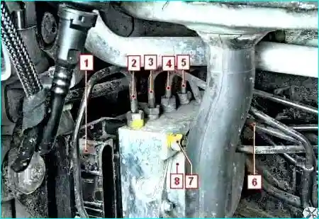
Fig. 6. ABS hydro-electronic control unit: 1 — hydro-electronic unit connector; 2 — right front wheel brake cylinder line; 3 — left rear wheel brake cylinder line; 4 — right rear wheel brake cylinder line; 5 — left front wheel brake cylinder line; 6,7 — master cylinder lines; 8 — pump
The hydro-electronic control unit (Fig. 6) receives information about vehicle speed, direction of travel and road conditions from the wheel speed sensors, steering angle sensor and throttle position sensor.
After the ignition is switched on, the control unit supplies voltage to the wheel speed sensors.
The sensors use the Hall effect and generate a square wave output signal.
The signal varies proportionally to the rotational speed of the sensor's impulse ring, mounted on the outer CV joint housing.
Based on this information, the control unit determines the optimal braking mode for each wheel.
Brake system fittings and lines
The lines are connected between the master cylinder, the calipers and the hydraulic unit using metric threaded fittings.
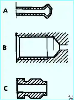
Fig. 7. Identification of brake system fittings: A – shape of the ends of steel or copper tubes; B – shape of the threaded recesses in the components; C – fittings with 11 mm hexagon
Brake fluid
Brake technology, particularly disc brakes (hollow pistons that transfer little heat, small fluid volume in the cylinder, floating calipers that eliminate the need for a relatively large fluid reserve in the least cooled part of the wheel), makes it possible to minimise the risk of «vapour lock» even with frequent and prolonged brake use (in mountainous areas).
Nevertheless, brake fluid characteristics deteriorate slightly during the first months of operation due to slight moisture absorption.
This necessitates the replacement of the brake fluid.
Brake fluid replacement interval
As the brake pads wear, the brake fluid level in the reservoir gradually decreases.
It is not necessary to compensate for this decrease; the level will be restored at the next brake pad replacement.
However, the level must not be allowed to fall below the minimum mark.
Mixing two incompatible brake fluids in the hydraulic system can cause significant fluid leaks, mainly due to seal deformation.
To prevent this, only use brake fluids that have been tested and approved by the technical department and that meet the SAE J 1703-DOT4 standard.
For optimal operating conditions of the brake system of «Renault» vehicles, it is recommended to use low-viscosity brake fluids at low temperatures (not exceeding 750 mm²/s at 40 °C).
Possible brake faults and how to fix them
Increased brake pedal travel
- Brake fluid leak from the floating caliper wheel cylinders — Replace the floating caliper.
- Air in the brake system — Bleed the system.
- Damaged hydraulic hoses or lines — Replace the hoses or lines and bleed the system.
Insufficient braking efficiency
- Brake pads contaminated with oil or grease — Replace the brake pads.
- Wheel cylinder pistons sticking — Check and replace the floating caliper if necessary.
- Brake pads completely worn — Replace the brake pads.
- Brakes overheating — Stop immediately and allow the brakes to cool.
- Use of low-quality pads — Use original pads.
- Loss of pressure in one circuit (accompanied by a sinking pedal) — Locate and repair the leak, bleed the system.
- ABS malfunction — Check the ABS system.
Incomplete release of all wheels
- No brake pedal free play — Replace the vacuum booster pushrod.
- ABS malfunction — Check the ABS system.
Brake drag on one wheel with the pedal released
- Piston sticking in the wheel cylinder due to dirt or corrosion — Replace the floating caliper.
- Master cylinder pistons sticking — Check and replace the floating caliper if necessary.
- Misalignment of the brake relative to the disc due to loose bolts — Tighten the bolts, replace damaged parts if necessary.
- Incorrect parking brake adjustment — Adjust the parking brake.
- ABS malfunction — Check the ABS system.
Vehicle pulling or swerving during braking
- Wheel cylinder piston sticking — Check and free the piston.
- Blocked line (due to a dent or clogging) — Replace the line.
- Discs or pads dirty or contaminated — Clean the brake components.
- One brake circuit not working (accompanied by reduced braking efficiency) — Replace damaged parts and bleed the system. If this does not fix the problem, check the ABS.
Increased brake pedal effort during braking
- Vacuum booster faulty — Replace the booster.
- Hose connecting the vacuum booster and the intake manifold damaged or loose — Replace the vacuum hose.
Brake squeal or vibration
- Brake pads contaminated with oil or grease — Replace the brake pads. Eliminate the cause of fluid or grease contamination.
- Brake pads worn — Replace the brake pads.
- Excessive disc runout or uneven wear (felt as pedal vibration) — Replace the disc if its thickness is below the service limit.


