


Install the mounting plate (B.Vi.1581) on the stand (Desvil).
Install the gearbox on the mounting plate (B.Vi.1581) (Fig. 1).
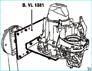
Fig. 1. Installing the gearbox on the mounting plate
Remove the clutch slave cylinder.
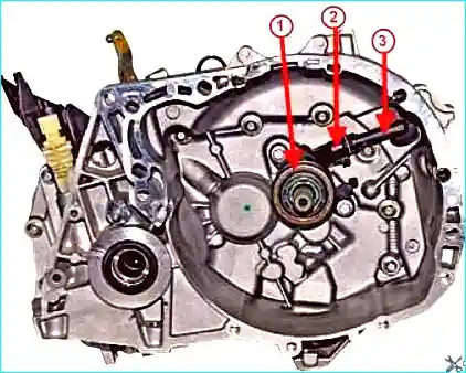
Fig. 2. Clutch housing: 1 - clutch release bearing, 2 - clutch slave cylinder, 3 - hydraulic fluid supply pipe
Unscrew the bolts located inside the housing (Fig. 2).
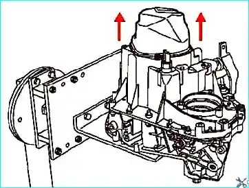
Fig. 3. Removing the rear cover
Remove the rear cover strictly along the horizontal axis of the gearbox, as it includes a lubricant capsule located in the input shaft bore (Fig. 3).
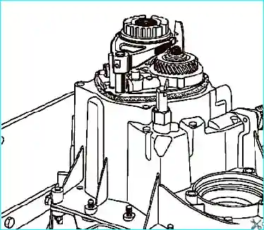
Fig. 4. Engaging first and fifth gears
Engage first gear using the gear lever, and fifth gear by moving its fork along the selector rod (Fig. 4).
Unscrew the output shaft bolt and the input shaft nut.
Using the drift (B.Vi.31-01), drive out the fifth gear fork pin.
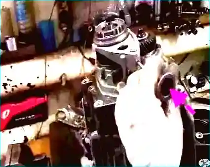
Fig. 5. Removing the fifth gear fork pin
Remove the fifth gear fork and synchroniser sleeve.
Extract the fifth gear hub using the tool (B.Vi.1170).
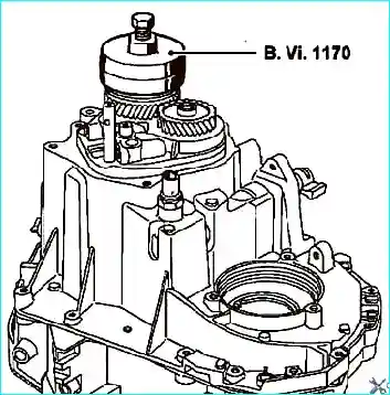
Fig. 6. Removing the hub
Position the tool synchroniser sleeve (B.Vi.1170) in the fifth gear engaged position, turning it so that the splines of the sleeve and hub align.
Remove the tool together with the hub (Fig. 6).
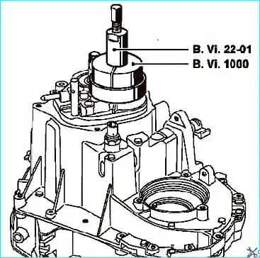
Fig. 7. Removing the fifth gear fixed gearwheel
Extract the fifth gear fixed gearwheel using the tools (B.Vi.22-01 and B.Vi.1000) (Fig. 7).
Remove the external gearbox housing bolts.
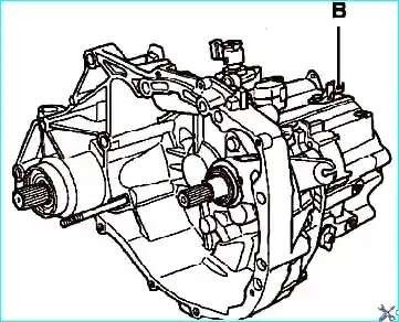
Fig. 8. Removing the speed sensor
Remove the speed sensor B (for the JH1 semi-automatic transmission) (Fig. 8).
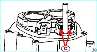
Fig. 9. Holes (C) to be blocked
It is recommended to place two magnets or to block holes C in order to avoid losing the detent balls and springs of the 1/2 and 3/4 selector rods (Fig. 9).
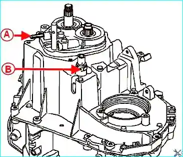
Fig. 10. Removing the reverse gear selector rod and switch
Remove the reverse gear selector rod A and the reverse gear switch B (Fig. 10).
Apply outward force to the selector rod.
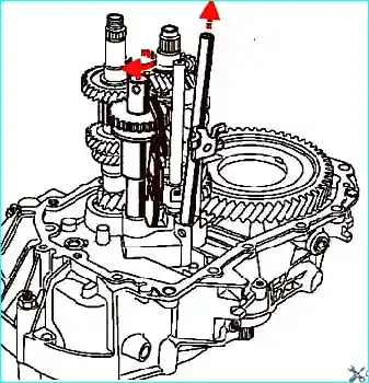
Fig. 11. Removing the selector fork rod «Reverse, fifth gear»
Disconnect and remove the gearbox housing.
Turn the reverse gear shaft assembly to the left and remove the selector fork rod «reverse/fifth gear» (Fig. 11).
Lift the input shaft slightly and remove the reverse gear shaft assembly (Fig. 12).
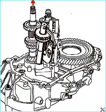
Fig. 12. Removing the reverse gear shaft assembly
Disconnect the 3/4 fork pins using the tool (B.Vi.949) and remove the 3/4 rod and fork assembly, together with the input and output shafts with the 1/2 rod and fork (Fig. 12).
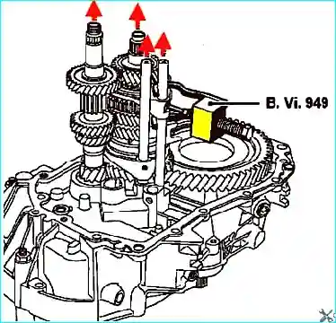
Fig. 13. Removing the 3/4, 1/2 rod and fork assembly
Simultaneously remove the input and output shaft assembly with the 1/2 rod and fork (Fig. 13).
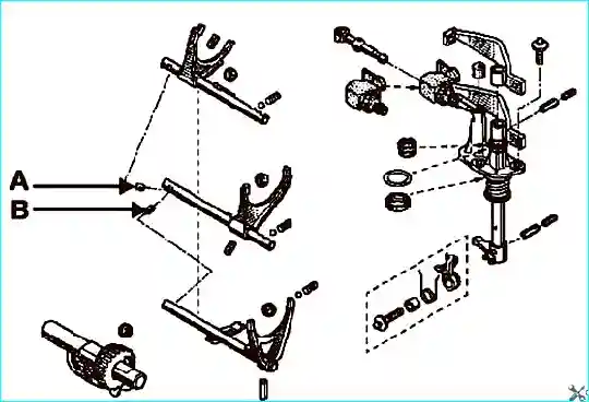
Fig. 14. Removing the locating pins
Removing the gears
Clamp the output shaft in a vice with soft jaws, then remove all the gears.
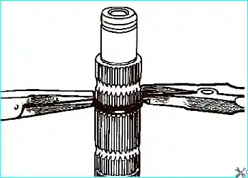
Fig. 15. Removing the retaining rings
When removing and installing retaining rings, use circlip pliers on one side and flat-nose pliers on the other (Fig. 15).
Inspecting the components
The teeth of the gears and synchroniser sleeves must not be excessively worn or have burrs.
Also, ensure that there are no signs of scoring or excessive wear on the shaft surfaces and the internal bores of the gears.
It is recommended to mark the position of the synchroniser sleeves relative to the hubs.
Replacing the bearings in the gearbox housing
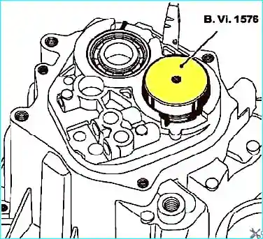
Fig. 16. Pressing the bearing into the housing
Spread the retaining rings using the appropriate pliers and press the bearing into the housing using the tool (B.Vi.1576) (Fig. 16).
Disassembly of the JH3 gearbox can be found in the article – «JH3 Gearbox Disassembly».


