Electrical equipment circuits are protected by fuses, Headlights, fan motors, fuel pump and other powerful consumers are connected via relays.
Fuses and relays are installed in mounting blocks located in the passenger compartment and in the engine compartment.
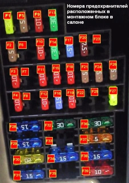
Fuses in the passenger compartment
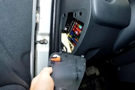
In the passenger compartment, the mounting block is installed on the left side of the instrument panel under the cover.
Before you replace a blown fuse, you need to find out the cause of its blown.
Do not replace the fuse with a jumper or a fuse with a higher current rating - this may damage electrical appliances and cause a fire.
To replace the fuse in the car, open the cover in the instrument panel
Remove the replaceable fuse with tweezers
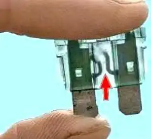
The figure shows a blown fuse (the jumper shown by the arrow is blown).
To replace the fuse, install a spare fuse of the same rating and color.
Fuses in the engine compartment
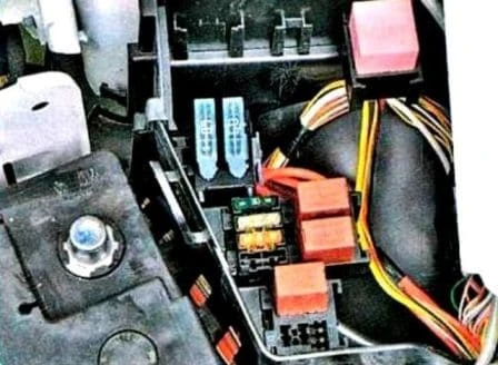
In the engine compartment, fuses and relays are located on the right and left sides of the battery.
To check or replace the fuse in the mounting block in the engine compartment
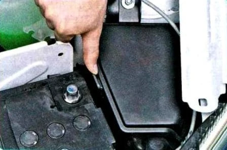
Press the lock of the cover of the mounting block
Remove the cover
If you need to replace a relay or fuse, remove it by swinging it from side to side
Install the parts in reverse order.
Methods for checking car electrical circuits
When replacing fuses, it is forbidden to use screwdrivers and metal tools - this can cause a short circuit in the circuits of electrical equipment.
It is forbidden to disconnect the battery while the engine is running, violation of this rule will cause failure of the voltage regulator and elements of the car's electronic equipment.
In order to avoid failure of the diodes of the generator rectifier unit, it is forbidden to check them with a megohmmeter or a test lamp supplied with a voltage of more than 12 V, and also to check the electrical circuits on the car with such devices without disconnecting the wires from the generator.
It is necessary to check the insulation resistance of the generator stator winding with increased voltage on the generator removed from the car, with the stator winding terminals disconnected from the rectifier unit.
When carrying out electric welding work on a car, it is necessary to disconnect the wires from the terminals of the battery and the generator, as well as the blocks with wires from the electronic engine control unit.
Do not touch the elements of the ignition system and high-voltage wires while the engine is running.
Do not run low voltage wires in the same bundle as high voltage wires.
Regularly clean the battery terminals and cable lugs from oxides and dirt.
When recharging the battery with the charger, disconnect the wires from the battery terminals.
A typical electrical circuit may include a main electrical element (consumer), various switches, relays, electric motors, fuses, fuses or circuit breakers, wiring related to this element, and connectors used to connect the main element to the battery and body - weight.
Before you start troubleshooting in any electrical circuit, carefully study the corresponding circuit in order to visualize its functional purpose as clearly as possible.
The circle of troubleshooting is usually narrowed by gradually identifying and eliminating normally functioning elements of the same circuit.
If several elements or circuits fail at the same time, the most likely cause of the failure is a blown fuse or a broken contact with ground ”(different circuits in many cases can be connected to one fuse or ground terminal).
Electrical equipment failures are often due to the simplest causes, such as corrosion of connector contacts, fuse failure, fuse blown, or relay damage.
Visually check the condition of all fuses, wiring, and connectors in the circuit before proceeding to a more detailed check of the health of its components.
When using diagnostic tools for troubleshooting, carefully plan (according to the attached electrical diagrams) where and in what sequence the device should be connected in the circuit for the most effective troubleshooting.
The main diagnostic tools include an electrical circuit tester or voltmeter (you can also use a 12-volt test lamp with a set of connecting wires), an open circuit indicator (probe) that includes a lamp, its own power source and a set of connecting wires.
In addition, you should always have a set of wires in the car for starting the engine from an external source (the battery of another car), equipped with crocodile clips and preferably an electrical circuit breaker.
They can be used for shunting and connecting various elements of electrical equipment when diagnosing a circuit.
As already mentioned, before starting to check the circuit using diagnostic equipment, determine the connection points from the diagrams.
Checking the presence of supply voltage is carried out in case of an electrical circuit failure.
Connect one of the circuit tester leads to either the negative battery terminal or make good contact with the vehicle body.
Connect the other tester lead to the terminal of the circuit under test, preferably closest to the battery or fuse
If the tester's control lamp lights up, there is supply voltage on this section of the circuit, which confirms the health of the circuit between this point of the circuit and the battery.
In the same way, explore the rest of the chain.
Detection of a supply voltage failure indicates the presence of a fault between this point in the circuit and the last one previously checked (where the supply voltage was).
In most cases, the cause of failure is loosening of the connectors and damage to the contacts themselves (oxidation).
Assignment of the fuses in the passenger compartment
No. (Amps) Protected circuit
- F1(20) Windshield wiper
- F2(5) Instrument cluster, ECU
- F3(10/20*) Reversing light switch
- F4(10) Electronic immobilizer (airbag/pretensioner* control unit*)
- F5(10) Automatic transmission
- F7(-) Trailer
- F9(10) Left headlight (low beam)
- F10(10) Right headlight (low beam)
- F11(10) Left headlight (high beam)
- F12(10) Right headlight (high beam)
- F13(30) Rear power windows
- F14(30) Front power windows
- F15(10) ABS control unit
- F16(15) Heated front seats
- F17(15) Beep
- F18(10) Port marker light, hazard switch, cigarette lighter
- F19(10/7.5*) Starboard position light
- F20 (7,5) Rear fog light switch
- F21(5) Heated exterior mirrors
- F23(-) Burglar alarm location
- F24(5) Power steering
- F25(5) Gas appliances
- F26(5) Airbag and pretensioner control module
- F27(20) Rear wiper, reversing light switch
- F28(15) Interior lighting
- F29(15) General power
- F30(20) Blocking opening body parts
- F31(15) Fog lights
- F32(20) Heated rear window
- F36(30) Electric fan for heating (air conditioning) and interior ventilation
- F37(5) Power door mirrors
- F38(15/10*) Car radio
- F39(10/30*) Heating (air conditioning) and interior ventilation systems
*only for cars up to 2009 release. F6, F8, F22, F33-35 - reserve.
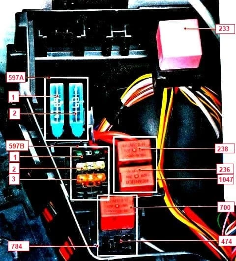
Assignment of relays and fuses in the engine compartment
Relay/Fuse Box No. (Current A) Purpose
597A
F1(60) Burglar alarm, outdoor light switch, daytime running light relay
F2(60) Ambient light switch, passenger compartment fuse box
597B
F1(30) Relay board power supply
F2(25) Injection relay supply circuit
F3(5) Injection relay supply circuit, engine control module
784
474(20) A/C compressor start relay
700(20) Electric fan relay
1047
236 Fuel pump relay
238 Injection blocking relay
Separate relay 233 Heater fan relay
Searching for a short circuit
One of the methods for finding a short circuit is to remove the fuse and connect a probe lamp or voltmeter instead.
There must be no voltage in the circuit. Pull the wiring while watching the probe lamp.
If the lamp starts flashing, then there is a short to ground in this wiring harness, possibly caused by chafing of the wire insulation.
A similar test can be carried out for each of the components of the electrical circuit by turning on the appropriate switches.
Checking the reliability of contact with ground
Disconnect the battery and connect one of the wires of the probe lamp, which has an autonomous power source, to a point with known good contact with the "ground", connect the other wire of the lamp to the wire harness or connector contact to be checked.
If the lamp lights up, ground contact is good (and vice versa).
Checking for breaks
The test is carried out to detect open circuits.
After disconnecting power to the circuit, test it with a self-powered test lamp.
Connect the probe wires to both ends of the circuit.
If the test lamp lights up, there is no open circuit, If the lamp does not light up, then this indicates an open circuit.
Similarly, you can check the health of the switch by connecting the probe to its contacts.
When the switch is turned to the ON position, the probe lamp should light up.
Localize the breakpoint
When diagnosing a section of an electrical circuit that is suspected of being open, visually detecting the cause of the malfunction turns out to be quite difficult, since it is difficult to visually check the terminals for corrosion or a violation of the quality of their contacts due to limited access to them (usually the terminals are closed by the contact connector housing).
A sharp twitch of the body of the wiring harness block on the sensor or the wiring harness itself in many cases leads to contact restoration.
Keep this in mind when trying to isolate the cause of a suspected open circuit failure.
Unstable failures may be due to oxidation of the terminals or poor quality of the contacts.
Diagnosing malfunctions in electrical circuits is not a difficult task, provided that it is clearly understood that electric current is supplied to all consumers (lamp, electric motor, etc.) from the battery through wires through switches, relays, fuses, fuses, and then returns to the battery through the mass (body) of the car.
Any problems related to the failure of electrical equipment can be caused by the interruption of the supply of electricity to them from the battery or the return of current to the battery.


