Generator repair consists of disassembling and replacing defective parts. In this generator, you can replace bearings, solder brushes, replace the voltage regulator unit and other parts
If the generator on the car has been in operation for a long time, then of course it will be easier to replace the generator with a new one
Disassembly and assembly of the generator, in principle, is not difficult, especially for those who have previously disassembled and assembled generators of other car brands.
To disassemble and assemble the generator, you will need tools: wrenches for 7, for 10, a ring wrench for 27, a Torx T50 key, a tester, a puller, a hammer, screwdrivers
We remove the generator from the car, as described in the previous article - Removing and installing the generator of a Hyundai Solaris car
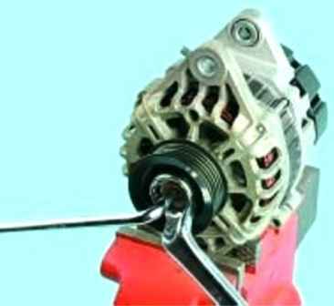
We unscrew the pulley fastening nut, keeping the generator shaft from turning (the thread is ordinary right-handed)
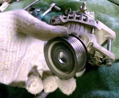
Remove the pulley from the generator shaft
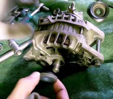
Remove the spacer washer (we look at which side the washer was installed so that it can also be installed during assembly)
The alternator pulley is fixed from turning on the rotor shaft due to friction after tightening the nut of its fastening to the required torque. There are no keys in the connection.
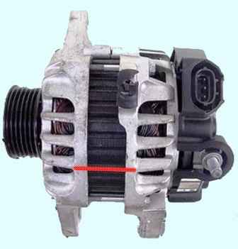
We mark the position of the stator and generator covers with a marker to ensure the correct position when assembling the generator
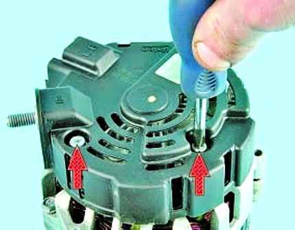
We unscrew the two screws securing the casing (on some generators, the casing is attached with three nuts)
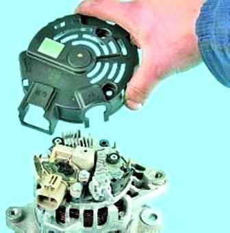
Remove the plastic cover
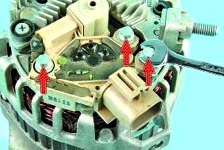
We unscrew the three bolts securing the brush holder with the regulator assembly
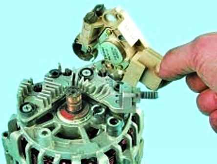
And remove the brush holder assembly with the regulator
Checking the protrusion of the brushes in a free state.
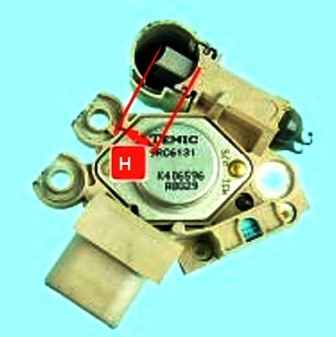
If the "H" dimension is less than or equal to 5 mm, replace the brushes or brush assembly.
Checking the ease of movement of the brushes in the brush holder
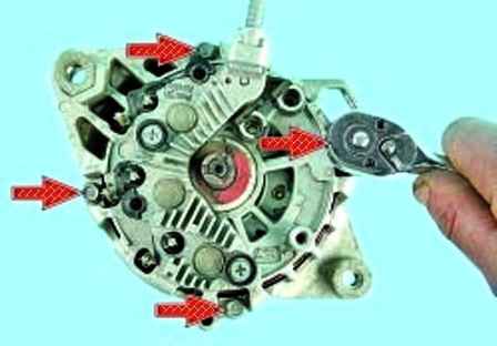
Unscrew the four tie bolts
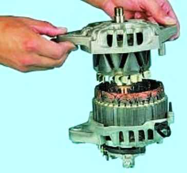
Remove the front cover with the rotor together
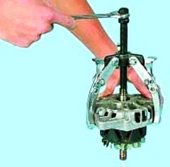
We press the rotor out of the front bearing
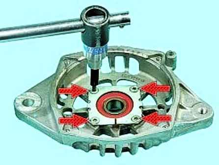
To replace the front cover bearing, unscrew the four screws securing the pressure plate
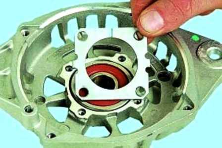
Remove the plate
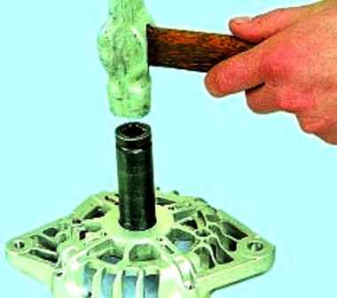
Press the bearing out of the cover
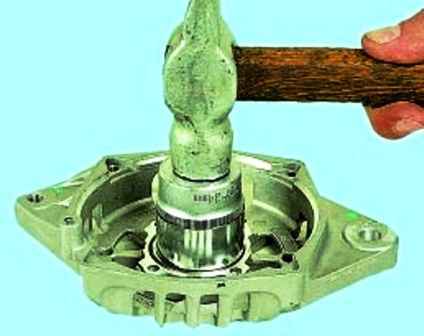
Using a suitable tool head, we press the new bearing into the cover, applying force to the outer ring
Check the ease of rotation of the front bearing. If play is felt during rotation of the bearing, then the bearing is replaced
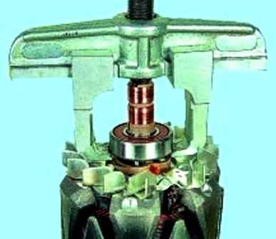
We press the bearing from the rotor shaft and install a new one, applying force to the inner ring
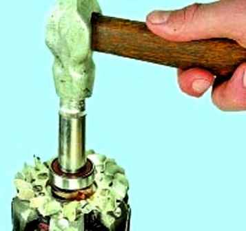
Using a suitable mandrel, we press in a new bearing, applying force to the inner ring of the bearing
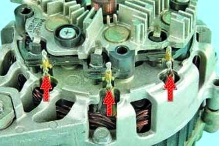
Unclench the contacts and disconnect the three leads of the stator winding from the rectifier unit
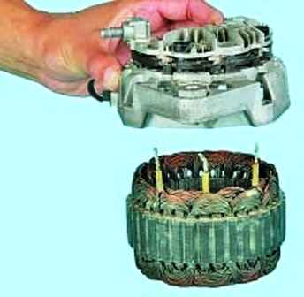
Remove the rectifier assembly with the cover
The cover and the rectifier unit are a single unit and are not subject to further disassembly, since the three diodes of the rectifier unit are pressed into the back cover and connected to the rectifier unit by welding
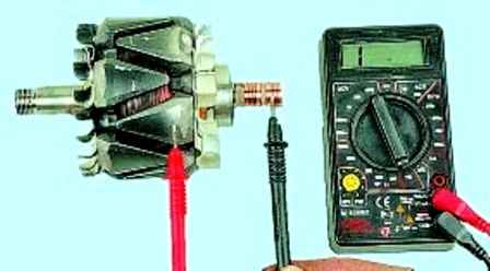
We connect the tester leads in turn to each slip ring and to the rotor housing, we check that the rotor winding is not shorted to the housing. The tester should show infinity
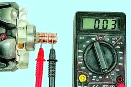
We connect the tester leads to the contact rings and check the resistance.
If the tester shows infinity, then there is a break in the rotor winding and the rotor needs to be replaced
We check the resistance of the rotor winding with a tester by connecting it to slip rings.
If the readings on the tester show infinity, then there is a break in the rotor winding and the rotor must be replaced.
We check the stator winding for an open circuit, alternately measuring the resistance between all winding terminals with a tester.
If the measured resistance tends to infinity, then the stator must be replaced.
We connect one tester probe to the stator housing, and connect the other in turn to each winding output.
Measured e resistance must be very large (should tend to infinity). Otherwise, replace the stator.
Check the "positive" diodes by connecting the "negative" (black) probe of the tester to the "plus" terminal of the generator, and connecting the "positive" (red) probe in turn to the three contact terminals of the diodes.
If the diodes are good, the tester will show 700-800 ohms.
Check the "negative" diodes by connecting the "negative" (black) probe of the tester to the "minus" terminal of the rectifier unit, and connecting the "positive" (red) probe in turn to the three contact terminals of the diodes.
If the diodes are good, the tester will show an infinite resistance.
Connect the "positive" (red) probe of the tester to the "minus" terminal of the rectifier unit, and connect the "negative" (black) probe in turn to the same three contact terminals of the diodes.
If the diodes are good, the tester will show 700-800 ohms.
If the tester shows low or close to zero resistance, the diode is “broken”; if the tester reading tends to infinity, regardless of the color of the connected probes, the diode is “open”.
In both cases, the rectifier unit must be replaced.
Assemble the generator in reverse order. When assembling, we orient the covers according to pre-made marks
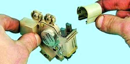
In order not to damage the brushes when installing the brush holder, remove the cover of the brush assembly
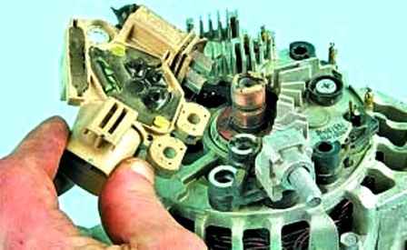
Install the brush holder assembly with the voltage regulator on the generator
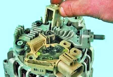
And install the cover of the brush assembly in place.
After assembly, we check the generator on the stand and install it on the engine


