Before removing any components of the fuel injection control system, disconnect the wire from the negative terminal of the battery
Do not start the engine if the cable lugs on the battery are loose.
Never disconnect the battery from the vehicle's electrical system while the engine is running.
When charging the battery, disconnect it from the car's on-board network.
Do not expose the ECU to temperatures above 65 °C in working condition and above 80 °C in non-working condition (for example, in a drying chamber).
Do not disconnect or connect wires to the computer while the ignition is on.
Before carrying out electric welding work on the car, disconnect the wires from the battery and the wiring harness pads from the computer.
Perform all voltage measurements with a digital voltmeter with an internal resistance of at least 10 MΩ.
Electronic components used in the fuel injection system are designed for very low voltage, so they can be easily damaged by electrostatic discharge.
To prevent damage to the computer, do not touch its terminals with your hands.
Removing and installing ignition coils
The engine is equipped with four ignition coils, each connected to a spark plug and located in the spark plug well of the cylinder head
If the coil is faulty, the fault indicator in the instrument cluster will light up
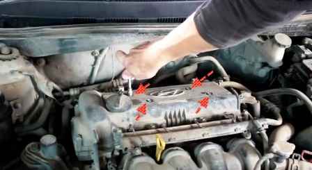
We unscrew the four bolts securing the cover of the candle wells
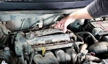
Remove the cover
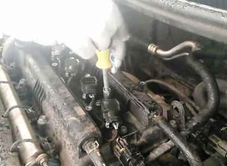
Unscrew the ignition coil bolt
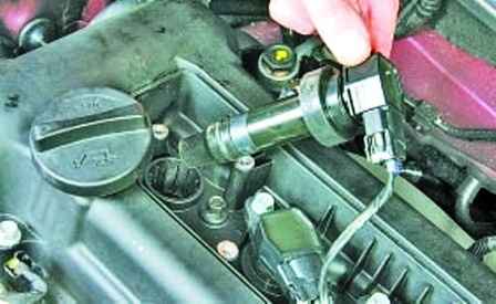
Remove the coil from the candle well
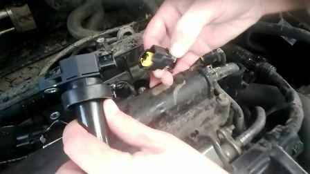
We press the latch and disconnect the wire block from the ignition coil
We also remove the remaining ignition coils
Install the ignition coils in reverse order
To check the coil, you need to install a tested spark plug into the coil and press it against the metal part of the engine.
Ask an assistant to crank the engine with the starter.
A strong spark should jump between the electrodes of the candle at regular intervals.
If there is no spark, then the coil is bad
Reliable contact of the spark plug body with ground is mandatory, since if an additional spark gap appears that is larger than the gap between the spark plug electrodes, the high-voltage circuit of the ignition coil or the engine control unit may be damaged.
Perform the specified test for no more than five seconds so as not to damage the exhaust gas converter if gasoline that has not been burned in the engine cylinders gets into it.
Replacement and maintenance of spark plugs
You will need a 16" spark plug wrench with a rubber bush to hold the spark plug
Remove the ignition coils as described above
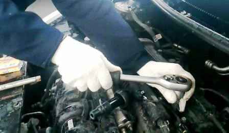
Unscrew the candles
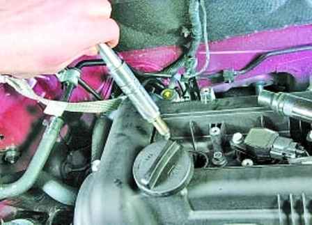
Removing candles from candle wells
We examine the candles and evaluate their condition and determine the operation of the cylinder by the candle
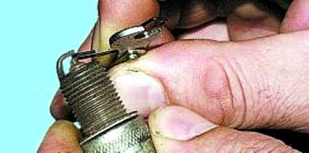
Check the gap between the spark plug electrodes with a round probe
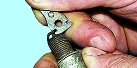
The gap for the spark plug NGK ZFR5F and NGK ZFR5F-11 should be 1.0-1.1 mm;
If the gap is different, adjust it by bending the side electrode
Install candles and all parts in reverse order
Removing and installing the electronic unit
Disconnect the negative battery terminal
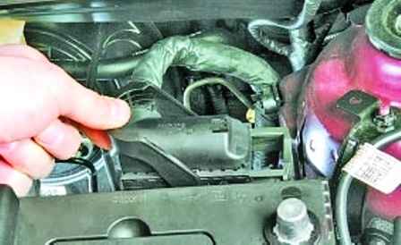
Having pressed the latch, we raise the fixing bracket
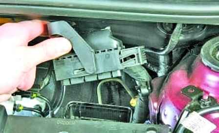
Disconnect the wiring harness from the electronic engine control unit
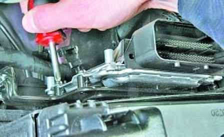
Unscrew the four fixing screws
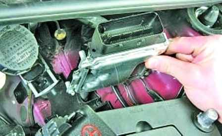
Remove the electronic engine control unit
Install the ECU in reverse order
Replacing the crankshaft sensor
The action of the sensor is based on the Hall effect.
The sensor is mounted at the rear of the engine, opposite the drive ring on the flywheel.
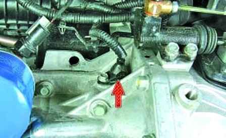
The driving ring is a gear wheel with cavities.
Two teeth are sheared to create a synchronization pulse ("reference" pulse), which is necessary to coordinate the operation of the control unit with the TDC of pistons in the 1st and 4th cylinders.
As the crankshaft rotates, the teeth change the magnetic field of the sensor, inducing AC voltage pulses.
The control unit determines the crankshaft speed using the sensor signals and sends pulses to the injectors.
If the sensor fails, the engine cannot be started.
The electronic unit memorizes the fault code
To remove the sensor, disconnect the negative battery terminal
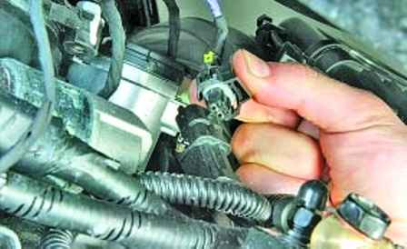
We press the latch and disconnect the wiring harness pads
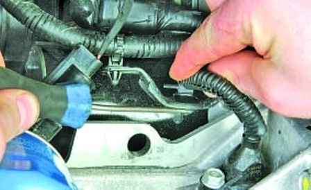
We press the latch and disconnect the wire harness holder from the bracket
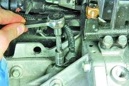
Unscrew the sensor mounting bolt
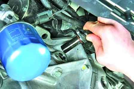
Remove the sensor from the hole in the cylinder block
Install the sensor in reverse order
Camshaft position sensor replacement
The sensor is installed in front of the cylinder head
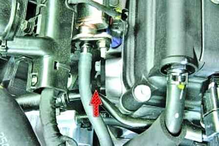
If there is a fault in the sensor circuit, the ECU stores the fault code and uses a bypass engine management program
Disconnect the wire from the negative battery terminal
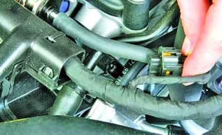
We press the latch and disconnect the block of wires from the sensor
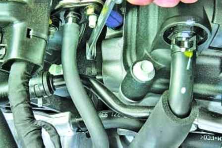
Unscrew the sensor mounting bolt
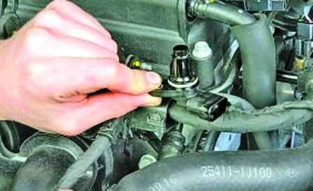
Remove the sensor from the hole in the cylinder head
Install the engine camshaft position sensor in reverse order
Replacing the coolant temperature sensor
The sensor is installed in the threaded hole of the distribution pipe housing on the wall of the engine block
If the sensor fails, the electronic unit memorizes the error and uses a bypass engine management program (calculates the approximate temperature value from the engine running time and air mass flow)
Disconnect the negative battery terminal
Drain the liquid from the cooling system (you can not drain the liquid if you quickly change the sensor or plug the hole with a plug)
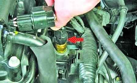
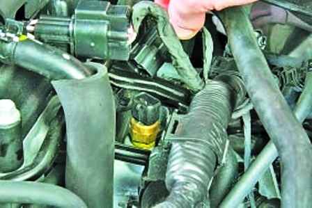
Squeeze the latch and disconnect the wire block from the coolant temperature sensor
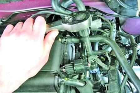
Unscrew the sensor
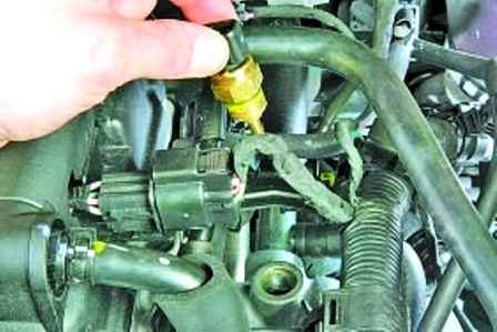
Remove the sensor from the hole in the distribution pipe body
To determine the health of the sensor, we lower it into hot water and check with a tester the change in resistance between terminals 1 and 3 of the sensor as the water cools, controlling the water temperature with a thermometer.
The nominal value of resistance against temperature is indicated in the table
Table. Resistance value versus temperature
Temperature - Resistance
-40° - 48.14 kOhm;
- 20 ° - 14.13-16.83 kOhm;
0° - 5.76 kOhm;
20 ° - 2.31-2.59 kOhm;
40° - 1.15 kOhm;
60° - 0.59 kOhm;
80° - 0.32 kOhm
Install the sensor in reverse order.
Apply sealant to the threaded surface of the sensor. Refill coolant.
Throttle position sensor
This is a variable resistor that is connected to the throttle shaft
The throttle position sensor is replaced as an assembly with the throttle assembly
Oxygen sensor replacement
The sensor is installed in the collector
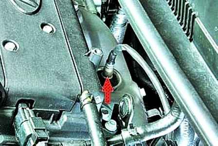
To unscrew the sensor, you will need a 22 socket with a cutout for the wiring harness
Disconnect the negative battery terminal
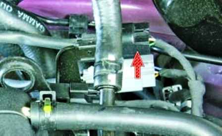
We press the lock of the wiring harness block and disconnect the wire blocks of the control oxygen concentration sensor
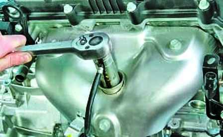
Unscrew the control oxygen concentration sensor
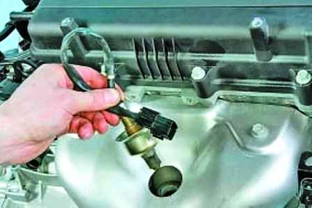
Remove the sensor (shown on the removed engine)
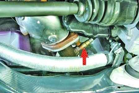
Install the sensor in reverse order
In the same way, we replace the diagnostic oxygen concentration sensor installed in the bellows
Replacing the knock sensor
The sensor is installed in the upper part of the cylinder block between the second and third cylinders.
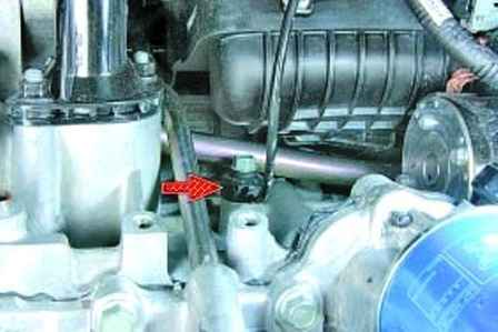
When a sensor fails, the ECU stores the error code and uses a bypass program with a reduced ignition angle to eliminate detonation
Disconnect the negative battery terminal
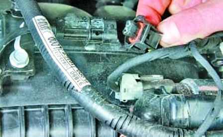
Disconnect the knock sensor wiring harness
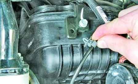
Remove the knock sensor wire holder from the bracket
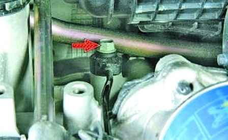
Unscrew the sensor mounting bolt
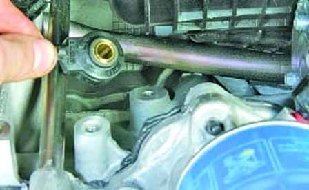
Remove the knock sensor
Install the knock sensor in reverse order
Replacing the absolute pressure sensor
The sensor is installed in the intake right pipe. It captures the change in pressure in the intake pipe depending on the load and engine speed and converts it into an output signal voltage.
The ECU supplies five volts to the sensor and processes the sensor signals from the signal transmission circuit.
Depending on the sensor signal, the electronic unit calculates the amount of air entering the engine.
Disconnect the negative battery terminal
We take the throttle assembly to the side without disconnecting the cooling system hoses from it
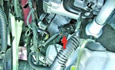
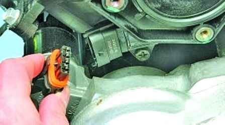
Disconnect the wiring harness from the sensor
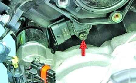
Remove the sensor mounting screw
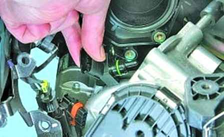
Remove the absolute pressure sensor
Install all parts in reverse order
Speed sensor replacement
The vehicle speed sensor is mounted on the gearbox.
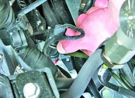
The principle of operation of the sensor is based on the Hall effect.
The sensor outputs rectangular voltage pulses to the electronic unit, the frequency of which is proportional to the speed of the drive wheels
Disconnect the wire from the negative battery terminal
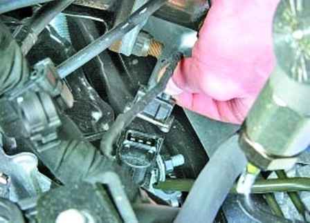
Squeeze out the retainer bracket
Disconnect the wiring harness from the speed sensor
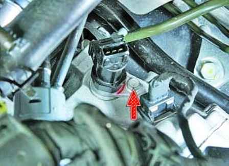
Unscrew the mounting bolt
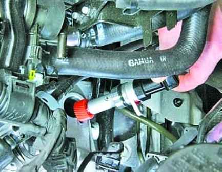
Remove the sensor from the gearbox hole
Install the sensor in reverse order
Removing and installing the phase regulator valve
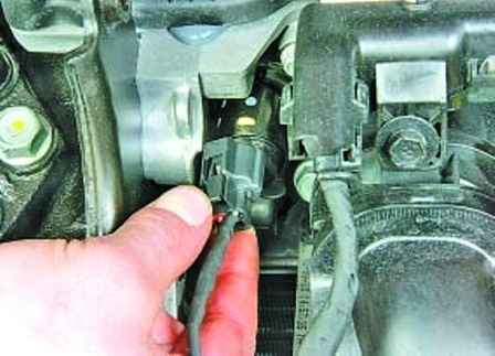
Squeeze the retainer of the valve block wires of the variable valve timing system
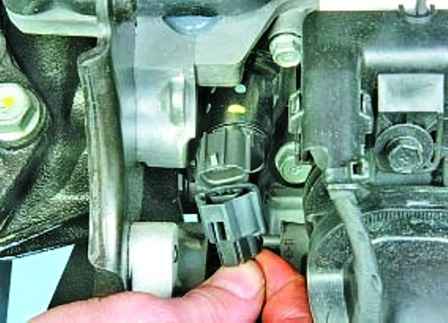
Disconnect the wire block from the phase regulator valve
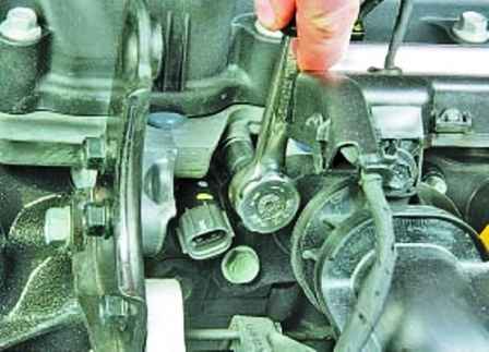
Unscrew the valve mounting bolt
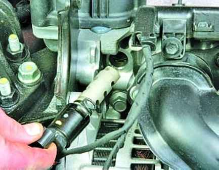
Remove the solenoid valve variable valve timing systems from the cylinder head
Install the new solenoid valve in reverse order
Possible ECU malfunctions and solutions
Fault Remedy
Knock knocks in the engine when accelerating the car
Knock sensor defective - Check and if necessary replace the knock sensor.
Check sensor contacts and connections
Fill with low octane gasoline - Fill with high-quality gasoline
Poor engine response to changes in throttle position, when starting off and accelerating
Faulty throttle position sensor - Check wiring connection
Inlet manifold absolute pressure sensor defective - Check the sensor, the contact connection with the wiring and the fit of the sensor in the intake pipe
Rough idling, increased vibration and stalling
Lean air-fuel mixture due to an increase in the signal voltage of the oxygen concentration sensor, due to the formation of deposits on the sensor bulb - If there is a white powdery coating on the sensor, replace the sensor
Throttle stuck open - Remove stuck throttle
Coolant temperature sensor or circuit malfunction - Check and if necessary replace the sensor. Check sensor contacts


