
The power supply system consists of two fuel tanks, fuel lines, a switching valve, a fuel pump, a sediment filter, a fine fuel filter, a carburetor with a throttle and air damper drive, an air filter
In modifications with a preheater, an electric fuel pump is included in the power supply system in parallel with the mechanically driven fuel pump.
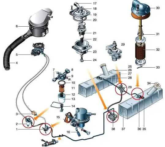
Power supply system: 1 - fuel pump; 2* - fine fuel filter with a replaceable filter element; 3* - fuel fine filter (non-separable); 4 - air intake hose; 5 - carburetor; 6 - air filter; 7.8 - fittings; 9 - cover; 10 - gasket; 11 - filter element; 12 - spring; 13 - glass-sump; 14 - holder of the glass-sump; 15 - fuel pump gasket; 16 - fuel pump manual drive lever; 17.18 - fittings; 19 - cover; 20 - gasket; 21 - filter element; 22 - spring; 23 - filter housing; 24 - threaded drain plug; 25 - filler neck; 26 - left fuel tank; 27, 35 - fuel gauge sensors; 28, 36 - fuel intakes; 29 - valve for switching fuel tanks; 30 - cover; 31 - spring; 32 - mesh filter; 33 - locking pin; 34 - filler cap; 37 - right fuel tank; 38 - sediment filter * It is possible to install a collapsible or non-collapsible fine fuel filter.
The fuel, under the action of the vacuum created by the fuel pump, passes through the fuel intake grid, then enters the sediment filter housing through the fuel line and the switching valve.
Water and large mechanical particles remain in the housing, and the fuel passes through the filter element, which consists of a set of thin steel plates, and is fed through the fuel line to the fuel pump.
After the pump, the fuel passes through the fine filter element and enters the carburetor.
The air necessary for the formation of the working mixture is supplied to the carburetor through the air filter.
Fuel tanks
Fuel tanks are rectangular steel, located on both sides of the car frame.
The tanks are attached to the frame spars from the outside using brackets and clamps. Cardboard spacers are placed between the clamps and the tank.
The tanks are connected by fuel lines to a switch valve installed under the driver's seat.
It can be used to switch the fuel intake from one tank to another.
The capacity of one tank is 39 liters.
At the top of each tank there is a fuel pickup, consisting of a tube and a brass mesh filter, as well as an electric fuel gauge sensor.
In some modifications, a drain hole with a threaded plug is located at the bottom of the tank.
The plastic filler cap has inlet and outlet valves to prevent underpressure and overpressure inside the tank.
On some vehicles, the fuel filler neck is equipped with a retractable pipe for easy refueling.
From the outside, the fuel filler hatch is closed with a cap.
Fuel lines
The fuel lines are made of rubber hoses and a copper tube.
The hoses are connected to the fuel pump, the fuel tank switching valve, the sediment filter through fittings with union nuts.
On the branch pipes of the fuel intakes, the carburetor and the fuel fine filter, the hoses are fixed with clamps.
The copper tube is connected at one end through the fitting to the sump filter, and at the other end is inserted into the rubber hose and tightened with a clamp.
Fuel filter sump
The fuel filter-sump is installed on the left side member of the frame in front of the fuel tank and is designed to separate water and mechanical impurities larger than 0.05 mm from the fuel.
To clean the fuel from mechanical impurities, the filter is equipped with a filter element consisting of a set of thin metal plates.
To remove sediment from the bottom of the filter housing there is a drain hole with a screw plug.
Fuel pump
The fuel pump is diaphragm, driven by an eccentric on the engine camshaft.
It is possible to install a pump of one of three models: B9V (451-1106010-40), 900-1106010 and 2105-1106010-50.
The fuel pump consists of a housing, a valve block cover and a drive lever. The valve block is installed in the pump cover.
A filter made of fine brass mesh is located above the suction valves.
To fill the carburetor with fuel when the engine is not running, the pump has a manual drive lever.
To control the tightness of the diaphragm and prevent fuel from entering the crankcase, the pump housing has a drain hole.
Filter thin fuel cleaning
The fuel fine filter can be used in two types: collapsible, with a replaceable filter element and non-collapsible.
The dismountable fuel filter is mounted on the cylinder head bracket.
It consists of a housing, a rubber gasket, a sealing rubber bushing, a ceramic or paper filter element, a spring, a plastic sump cup and sump cup attachment parts.
A filter with a plastic non-separable housing and a paper filter element is installed on a hose that supplies fuel to the carburetor.
Air filter
Air filter - dry type, with a replaceable filter element made of non-woven synthetic material, mounted on the bracket of the cylinder head.
The filter is equipped with a corrugated air intake hose connected to a metal pipe located on the radiator casing bracket on the right.
At an ambient temperature below 5 ° C, to supply heated air to the carburetor, disconnect the corrugated hose from the filter pipe, and turn the damper on the exhaust manifold to the "winter" position.

Why use the “10” key to loosen the nut that fixes the damper.
The air filter cover has two pipes for connecting hoses of the crankcase ventilation system.

If the cylinder head cover, due to a misconfiguration, has two pipes for removing crankcase gases, then to prevent unfiltered air from entering the intake pipe, it is necessary to plug the unused small pipe of the air filter cover in any way possible (for example, squeeze it with pliers).
Throttle actuator
The throttle control drive consists of a pedal, a system of rods and levers, tips of adjusting nuts, couplings and a spring.
In addition, the cars have a manual throttle actuator. It consists of a handle on the instrument panel, a sheathed rod, a bracket and a lever.
The carburetor choke is controlled by a knob located also on the instrument panel. It is connected to the damper lever by a sheathed rod.
When the handle is in its rest position (recessed), the choke is fully open.

")
")
")
")
")
")
")
")