
Depending on the engine model, various modifications of the K-151 carburetor are used, differing in the flow sections of the jets and minor design changes
The carburetor of the K-151 family is an emulsion type, two-chamber, with a falling flow and mechanical sequential opening of the throttle valves.
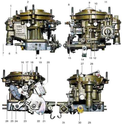
External views of the carburetor: 1 - screw-plug of the float axis; 2 - threaded plug of the fuel jet of the transition system of the second chamber; 3 - vacuum extraction fitting to the vacuum regulator of the ignition distributor; 4 - vacuum extraction fitting to the electromagnetic valve of the EPHX system; 5 - fitting of the crankcase ventilation system; 6 - fitting bolt; 7, 29 - fuel supply fitting; 8 - air damper drive lever; 9 - air damper; 10 - threaded plug of the emulsion jet of the idle system; 11 - accelerating pump; 12 - economizer housing; 13 - fitting for vacuum control of the exhaust gas recirculation valve; 14 - screw for adjusting the composition of the mixture at idle (quality screw); 15 - screw for adjusting the idle speed of the crankshaft (quantity screw); 16 - adjusting screw for fastening the overhead lever of the starting device control cam; 17 - two-arm trigger lever; 18 - air damper axis lever; 19 - air damper drive rod; 20 - microswitch of the EPHX system; 21 - sector (throttle actuator lever); 22 - coupling spring of the sector free play; 23 - overhead lever of the starting device control cam; 24 - throttle lever of the second chamber; 25 - screw stop of the shutter lever of the second chamber; 26 - cam starter; 27 - lever for closing the air damper; 28 - air damper closing spring; 30 - accelerator pump drive cam; 31 - fitting for supplying vacuum to the economizer valve
The carburetor is attached to the intake manifold with four studs through two paronite gaskets, between which a stamped steel pan is installed.
The carburetor consists of three parts: a cover, a body and a throttle body.
Carburetor has:
- - main dosing systems of the first and second chambers;
- - idle system and transition system of the first chamber;
- - transitional system of the second chamber;
- - econostat;
- - accelerator pump;
- - launcher;
- - forced idle economizer system (EPKhH);
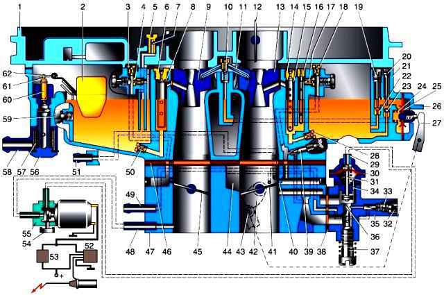
Carburetor diagram: 1 - cover; 2 - float; 3 - air jet of the transition system of the second chamber; 4 - fuel jet of the transition system of the second chamber; 5 - threaded screw-holder of the econostat atomizer; 6 - main air jet of the second chamber; 7 - econostat atomizer; 8 - emulsion tube of the main dosing system of the second chamber; 9 - small diffuser of the second chamber with atomizer; 10 - discharge valve; 11* - accelerator pump atomizer; 12 - air damper; 13 - small diffuser of the first chamber with atomizer; 14 - main air jet of the first chamber; 15 - emulsion tube of the main dosing system of the first chamber; 16 - block of fuel and air idle jets with an emulsion tube; 17 - emulsion jet of the idle system; 18 - idle air jet; 19 - adjusting needle on the jet of the drainage channel of the accelerator pump; 20 - stroke limiter of the ball valve of the accelerating pump; 21 - carburetor body; 22 - bypass (drainage) jet of the accelerator pump; 23 - accelerator pump valve ball; 24 - accelerator pump diaphragm spring; 25 - accelerator pump diaphragm; 26 - accelerator pump diaphragm cover, 27 - accelerator pump drive lever; 28 - main fuel jet of the first chamber; 29 - EPHX valve fitting; 30 - EPHX valve diaphragm; 31 - shut-off valve EPHKh; 32 - plastic quality screw turn limiter; 33 - screw for adjusting the composition of the mixture at idle (quality screw); 34 - unloading sub-diaphragm hole in the EPHX valve body, 35 - forced idle economizer case (idling unit); 36 - valve seat of the idle system; 37 - screw for adjusting the idle speed of the crankshaft; 38 - gasket, 39 - additional screw for adjusting the composition of the mixture on the main idling fuel supply branch (only on early modifications of carburetors); 40 - transitional slotted hole of the idle system; 41 - throttle valve of the first chamber; 42 - accelerator lever drive cam foot pump; 43 - accelerator pump lever roller; 44 - inlet window of the air channel of the idle system; 45 - throttle valve of the second chamber; 46 - heat-insulating type-setting gasket of the carburetor body; 47 - throttle body; 48 - vacuum extraction fitting to the EPHKh solenoid control valve; 49 - vacuum extraction fitting to the vacuum ignition timing controller; 50 - main fuel jet of the second chamber; 51 - vacuum extraction fitting to the exhaust gas recirculation valve; 52 - power circuit of the EPHX control unit; 53 - microswitch circuit of the EPHX system; 54 - filter on the vent fitting of the EPHX solenoid control valve; 55 - solenoid valve of the EPHX system; 56 - fitting bolt; 57 - fuel filter; 58 - fuel supply fitting; 59 - plug on the wall of the float chamber; 60 - shut-off valve of the float mechanism; 61 - locking needle earring; 62 - float tongue, and for carburetors installed on an engine with a displacement of 2.5 liters, the sprayer has one nozzle directed to the first chamber.
Float chamber - balanced, with plastic float.
Fuel is supplied to it through a strainer. Float mechanism with needle valve.
The float acts on the valve needle, blocking the channel and thereby maintaining the desired fuel level in the float chamber. There is no backflow of fuel into the tank.
The main dosing system consists of air and fuel jets, emulsion tubes, as well as sprayers installed in small diffusers of the carburetor chambers.
The idling system is autonomous, with adjustment of the amount and composition of the mixture, quantity and quality screws.
The idle system is equipped with a forced idle economizer (EPKhK), which cuts off the fuel supply during engine braking. This reduces the emission of harmful substances and reduces fuel consumption.
The transitional systems of the first and second chambers function at the moment of opening their throttle valves and ensure smooth switching on of the chambers.
The transition system of the first chamber is integrated with the idle system.
The carburetor's econostat, under the action of vacuum, supplies an additional amount of fuel through the atomizer to the second chamber at maximum power modes.
Accelerator pump of the diaphragm type, driven by the throttle valve axis of the first chamber.
When the throttle is suddenly opened, it enriches the mixture by injecting an additional portion of fuel into the first chamber of the carburetor, which ensures the acceleration of the car.
In the 2.9 liter engine carburetor, the accelerator pump nozzle has two nozzles that supply fuel to both chambers.
The starting device is a semi-automatic type, it consists of a pneumatic corrector, a system of levers and an air damper.
The choke must be closed before starting a cold engine using a manual actuator.
At the moment the engine is started, the pneumatic corrector, under the action of the vacuum that occurs in the intake pipeline, automatically opens the air damper to the required angle, ensuring stable operation of the engine during warm-up.