The car is equipped with a dry, single-disc, permanently engaged clutch with a hydraulically actuated release mechanism
Aperture clutch
The clutch consists of a crankcase, a clutch with a bearing and a fork, a drive disk assembly (basket), a driven disk, a main and a working cylinder, connected by a hose and a tube.

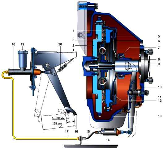
Diaphragm clutch with release drive: 1 - damper spring; 2 - flywheel; 3 - driven disk; 4 - pressure plate; 5 - casing; 6 - diaphragm spring; 7 - clutch release bearing (release bearing); 8 - clutch off; 9 - cover of the bearing of the input shaft of the gearbox; 10 - ball bearing; 11 - shutdown fork; 12 - support rings; 13 - clutch housing; 14 - working cylinder; 15 - hose; 16 - pedal; 17 - pipeline; 18 - main cylinder; 18 - tank; 20 - spring
The driving disk (basket) contains a casing in which a diaphragm spring, support rings and a pressure disk are installed.
A spring attached to the casing acts on the pressure plate with its edges.
The driven disc consists of a hub with a splined hole and two discs, one of which is riveted with leaf springs.
Friction pads are attached to them on both sides.
Curved leaf springs help to better fit the disc and additionally smooth out jerks in the transmission when the clutch is engaged.
For a smooth transmission of torque when starting the car and shifting gears, damper springs are installed in the disc windows.
The driven disc is pressed against the engine flywheel by the pressure plate of the basket.
Through friction linings that increase friction, the torque is transmitted to the driven disk and then to the input shaft of the gearbox, with which the driven disk is splined.
The clutch release actuator is used to temporarily disconnect the engine and transmission.
When you press the clutch pedal, the clutch master cylinder piston moves forward.
The displaced liquid enters the working cylinder through the tube and hose, pushing the piston with the rod out of it.
The rod acts on the shank of the fork, which rotates on a ball joint, moving the clutch release clutch along the gearbox bearing cover with the other end.
The clutch bearing presses on the ends of the petals of the diaphragm spring.
Deforming, the spring ceases to act on the pressure plate, which, in turn, on the driven one, and the transmission of torque stops.
Outside, the clutch mechanism is covered with an aluminum crankcase with a stamped steel pan (lower part of the crankcase).
The crankcase is attached to the engine block with six bolts and two amplifiers.
On the other hand, four studs are screwed into the crankcase for securing the gearbox.
The crankcase has a place for installing the clutch slave cylinder and a window for installing the fork.
Spring-lever clutch
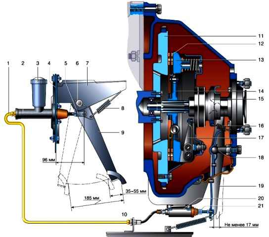
According to the principle of operation and design of most elements, a spring-lever clutch is similar to a diaphragm clutch.

Spring-lever clutch with shutdown drive: 1 - hydraulic drive pipeline; 2 - the main cylinder of the hydraulic drive; 3 - tank; 4 - partition of the engine compartment; 5 - fork of the main cylinder; 6 - pedal axis; 7 - bracket for clutch and brake pedals; 8 - pedal release spring; 9 - pedal; 10 - hydraulic drive hose; 11 - flywheel; 12 - friction linings of the driven disk; 13 - pressure plate; 14 - hub of the driven disk; 15 - clutch release clutch; 16 - coupling spring; 17 - pull lever, 18 - clutch release fork support; 19 - clutch release fork; 20 - working cylinder of the hydraulic drive; 21 - pusher of the working cylinder
The main difference lies in the design of the drive plate (basket), which consists of a pressure plate casing, clutch release levers and pressure springs.
The design of the drive plate ensures the transmission of torque through the clutch cover, as well as the centering of the pressure plate and its axial movement when the clutch is released.
The pressure plate is made with three protrusions, in the grooves of which the clutch release levers are installed on the axles.
The levers are connected to the clutch cover by support forks.
Spherical nuts are screwed onto the threaded part of the forks.
The shanks of the support forks are punched to prevent loosening of the nuts.
Nuts are pressed against the spherical surfaces of the casing by conical springs.
The pivoting of the support forks compensates changing the distance along the radius between the axes of the levers when the clutch is disengaged, and also allows the ends of the levers to self-align.
The axles of the levers are mounted on needle bearings.
Three rectangular holes are made in the clutch cover for the projections of the pressure plate.
The casing is attached to the flywheel with six bolts.
There are nine pairs of cylindrical pressure springs under the casing.
Bleeding the clutch release hydraulic drive and replacing the working fluid
We pump the hydraulic drive when replacing the working fluid, as well as to remove air from the system that got into it during the repair or replacement of individual components.
We do the work with an assistant.
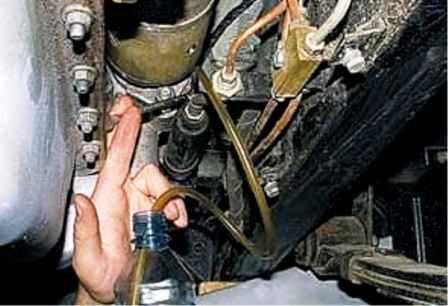
Removing the protective cap from the bleeder of the working cylinder of the hydraulic drive, we put a hose (preferably transparent) 30–50 cm long on the bleeder, immersing its end in a container filled with working fluid.
The assistant presses the clutch pedal three to four times at intervals of 1-2 seconds, and then keeps the pedal depressed.

With the “8” key, turn off the bleeder valve by 1/3–1/2 turn.
In this case, part of the working fluid and air bubbles are forced into the container, and the clutch pedal drops to the floor.
Without releasing the pedal, we wrap the bleed valve.
Repeat the operation until the bubbles come out of the hose completely.
At the same time, we constantly monitor the level of the working fluid in the reservoir of the main cylinder and top it up if necessary.
To replace the working fluid, unscrew the bleed valve and press the clutch pedal until the working fluid stops flowing out of the hose.
We wrap the fitting and fill in fresh working fluid into the reservoir of the main cylinder to the “MAX” mark, after which we pump the hydraulic drive, as described above
Possible clutch failures and solutions
Clutch does not fully disengage ("leads")
- Increased clutch pedal free play over 55 mm
Adjust clutch release actuator
- Deformed driven disk
Replace disk
- Air got into the hydraulic drive system
Bleed the system
- Destruction of parts of the driven disk
Replace disk
- Jamming of the hub of the driven disk on the splines of the input shaft
Remove the cause of jamming, lubricate the splines
- The adjusting screws of the pressure plate do not lie in a plane parallel to the plane of the flywheel
Disassemble clutch and adjust
- Increased gaps in the clutch drive
Replace worn parts
- The position of the clutch release pedal has not been adjusted
Adjust pedal position
Clutch slipping, i.e. not fully engaged (when the pedal is released)
- No free play of the clutch pedal
Adjust clutch release actuator
- Jamming of the pressure plate mechanism
Remove the cause of the jam or replace the drive
- Reducing the force of pressure springs or breaking them
Replace pressure springs
- Oiling work surfaces
Rinse rims and pads with clean gasoline
- Clutch overheating due to long slippage
Let the clutch cool down
- Clogging of the compensation hole of the main cylinder of the hydraulic drive
Clean the compensation hole and change the fluid if it is dirty
Unsmooth clutch engagement (with jerks and vibrations)
- Lubrication of friction linings
Replace friction linings or wash them in gasoline, sand them with fine sandpaper to remove protruding bumps.
Scrape the surfaces of the flywheel and pressure plate with the same sandpaper. Eliminate the cause of oiling
- Wear of friction linings to rivets
Replace friction linings
- The adjusting screws of the pressure plate levers do not lie in the same plane parallel to the plane of the flywheel
Disassemble clutch and adjust
- Uneven thickness of the driven disk
Grind or replace driven disc
Noise when pressing the pedal
- Clutch release bearing worn or out of lubrication
Lubricate the bearing, if the noise persists, replace the bearing
Clutch pedal won't stay up
- Broken release spring
Replace spring


