In the article, we will consider the design features of the engine cooling system and the replacement of the coolant of a UAZ car
The cooling system is closed, with forced circulation of liquid.
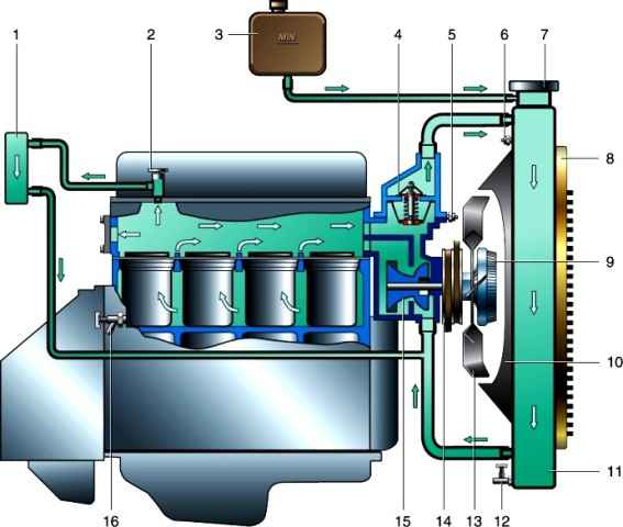
The system consists of a cylinder cooling jacket, pump, thermostat, radiator, fan, expansion tank and connecting hoses.
The system provides temperature and overheating sensors for the coolant.
The coolant is pumped into the cylinder block, passes through the channels into the head jacket and is directed through the thermostat through a large or small circulation circle, depending on the position of the thermostat valves.
If the liquid circulates in a large circle, after the thermostat it passes through the engine radiator, cools in it and again enters the pump through the lower radiator hose.
The small circle of circulation eliminates the radiator, which contributes to the rapid warming up of the engine after starting.
The centrifugal coolant pump is studded at the front of the unit.
The pump is driven by a V-belt from a pulley on the crankshaft.
The shaft rotates in a sealed, maintenance-free ball-roller bearing.
The tightness of the pump is ensured by a mechanical self-clamping seal (gland).
The thermostat is located in a separate housing on the cylinder head.
Thermostat sensing element is solid-filled.
Depending on the temperature of the coolant, it opens the lower or upper valve, directing the liquid through a large or small circle of circulation.
Operating a car with the thermostat removed is unacceptable, since in this case the liquid circulates mainly in a small circle, bypassing the radiator, which leads to engine overheating.
The radiator is brass, tubular-lamellar, consists of an upper and lower tank connected by flat tubes.
The radiator plug connects the cooling system through the intake and exhaust valves to the expansion tank.
This is necessary to compensate for changes in the volume of the liquid when it is heated and cooled.
A fan with a four-bladed impeller is mounted on the coolant pump hub directly or through a viscous coupling.
Viscous coupling is installed on some cars
The rotation of the fan impeller is transmitted through a special viscous silicone fluid poured into the clutch housing.
The clutch is controlled by a spiral thermostat mounted on the front of the clutch body.
As the temperature of the air behind the radiator increases, the slippage of the clutch on the hub decreases and the fan impeller starts to rotate faster.
When the engine is cold and at high speeds, the fan rotates more slowly, which reduces the warm-up time to operating temperature, reduces fuel consumption and reduces noise.
The expansion tank, made of polyethylene, is installed under the hood on the right in front.
In its plug there is a rubber membrane with a slot, which plays the role of inlet and outlet valves for communicating the cooling system with the atmosphere.
There is a minimum liquid level mark on the tank wall.
The coolant temperature indicator sensor is installed on the thermostat housing, and the fluid overheat sensor is in the upper radiator tank.
Information from the sensors is displayed on the instrument panel, where a temperature gauge and a signal lamp for overheating of the coolant are located.
The signal lamp lights up when the coolant reaches a temperature of 91–98 °C.
Coolant change
We install the car on a lift or a viewing ditch
Remove the front engine mudguard
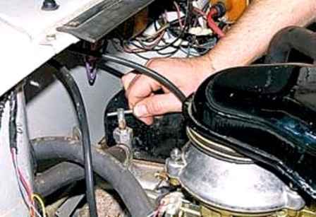
Opening the heater tap
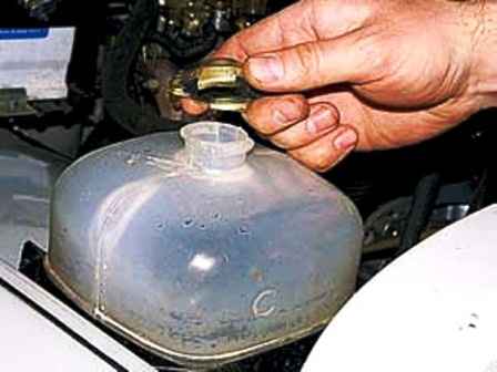
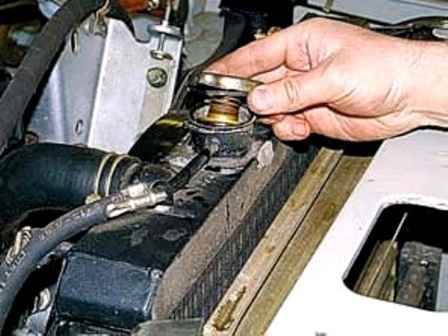
Unscrew and remove the radiator and expansion tank plugs
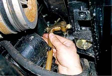
We put a hose of a suitable size on the radiator tap pipe, and, opening the tap, drain the liquid into a container with a volume of at least 14 l
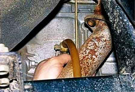
We put a hose on the pipe of the cylinder block valve and also drain the liquid from the block
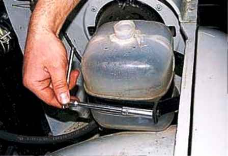
With a head of 10, unscrew the nut of the expansion tank clamp
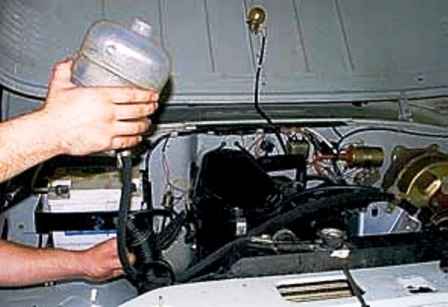
Having removed the corrugated air intake hose from the pipe of the radiator casing, we raise the tank to completely drain the liquid from its hose
Close all taps and install the expansion tank.
Pour new coolant into the system.
We fill the cooling system through the radiator, after which we install the plug of its filler hole in place.
Pour liquid into the expansion tank to a level 3–4 cm above the “min” mark.
Installing the plug of the expansion tank.
Starting the engine and letting it run for 2-3 minutes, add liquid to the expansion tank, bringing its level to normal


