


We remove the rear wheel drives during the dismantling of the rear final drive, when replacing the drives themselves, when replacing the dirt-protective covers of the inner and outer joints.
We also remove the wheel drives when replacing the drive oil seals in the rear final drive.
We carry out the work on an inspection pit or a trestle.
For the work the following tools will be required: a spanner and a socket 21, a socket 30, a wheel bolt spanner, a mounting spatula.
We engage the first gear in the gearbox (in an automatic gearbox we set to position "P") and place anti-rollback chocks under the front wheels.
We loosen the wheel bolts on the side being worked on.
We drain the oil from the rear axle final drive.
We raise the rear part of the car and install it on reliable supports.
We unscrew the wheel bolts and remove it.
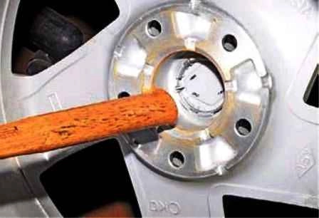
We push out the decorative cap with the hammer handle.
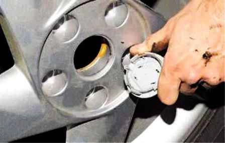
We remove it.
We put the wheel back in place and secure it with two bolts.
We lower the car onto the wheels and apply the parking brake.
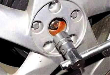
With a 30 mm socket we unscrew the hub bearing securing nut.
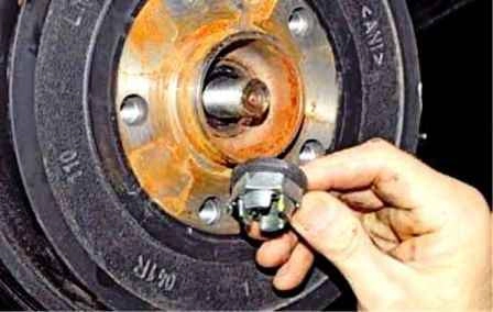
We remove the nut.
We remove the wheel and install the car on a stand.
We unscrew the nuts of the bolts securing two transverse and longitudinal arms of the rear suspension to the knuckle and take out the bolts.
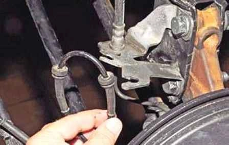
We bring out the rubber sleeves of the wires of the speed sensor.
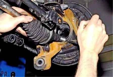
We bring the parking brake cable out of two plastic holders secured on the fuel tank.
We move the knuckle of the rear suspension of the shock absorber strut aside and bring the splined shank of the outer joint body out of the wheel hub.
At the same time we hold the wheel drive shaft so that the tripod does not come out of the inner joint body.
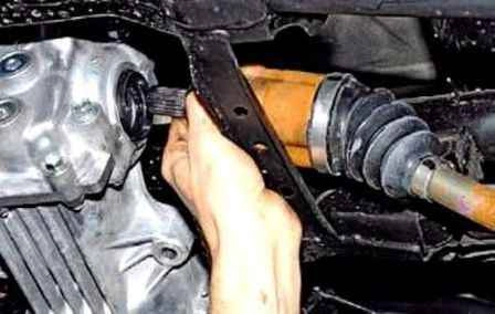
We bring the splined shank of the inner joint body out of the splines of the side gear of the differential.
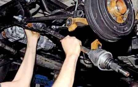
We remove the rear wheel drive.
We install the drive in the reverse order.
Removing the outer joint, replacing the cover
We remove the rear wheel drive, as described above.
We place the drive on the table.
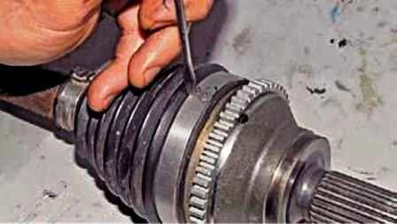
We direct the blade of a flat screwdriver into the joint of the lock of the large clamp, strike with a hammer on the handle of the screwdriver.
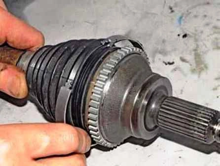
We open the lock and remove the clamp.
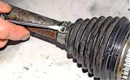
With a screwdriver we open the lock of the small clamp.
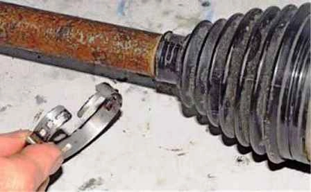
We remove the small clamp.
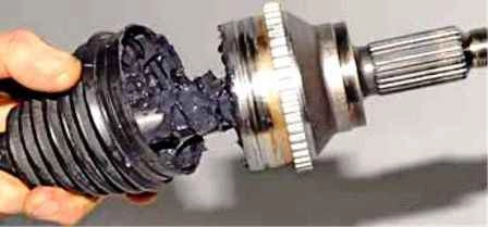
We remove the cover from the outer joint body and shift the cover along the shaft towards the inner joint.
We clamp the shaft in a vice.
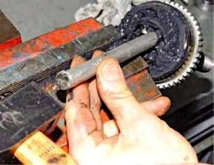
With a drift we knock the outer joint off the splines of the drive shaft, striking the end face of the cage and at the same time moving the drift around the circumference of the cage.
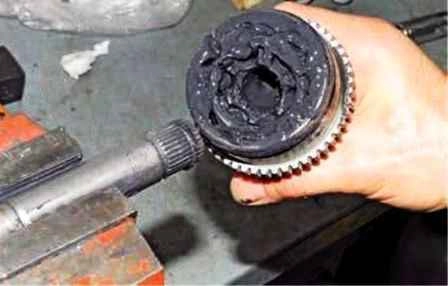
We remove the outer joint from the shaft.
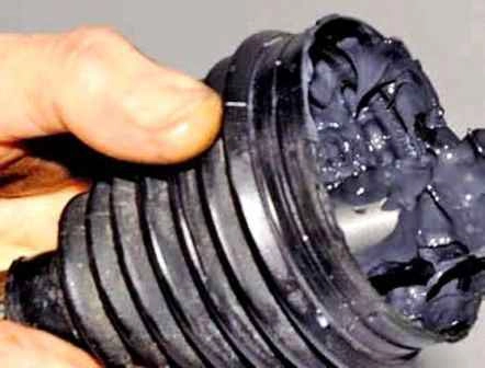
We remove the cover from the shaft.
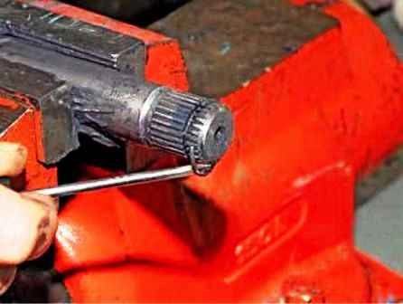
We prise up the circlip with a screwdriver.
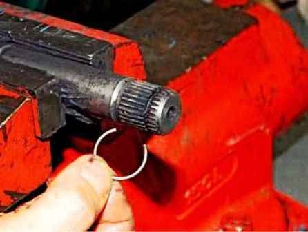
We take the ring out of the groove on the shaft.
If the joint is removed only for replacing the cover (when it is known that it was damaged recently and the CV joint has retained its serviceability), without dismantling the joint, we remove the old grease from the joint and wash it in kerosene.
We blow the joint with compressed air.
We inspect the balls, the cage, the race and the inner cavity of the body.
Scores, dents, cracks, traces of corrosion on the joint elements are not allowed — we replace such a joint.
We clean the shaft of the old grease and apply a thin layer of new grease to it. We put a new joint cover on the shaft.
We install a new circlip in the groove of the shaft.
We place and evenly distribute in the cavities of the joint body and its cover the required volume of new grease.
We put the joint on the shaft and, striking with a hammer through a spacer of soft metal on the splined shank of the joint, press the joint onto the shaft.
We check the fixation of the joint cage by the circlip.
We check the mobility of the joint — it must move without jamming.
We pull the cover onto the joint body so that the belts of the cover under the clamps are located in the corresponding places of the shaft and the joint body.
We secure the joint cover with new clamps.
The construction of the factory clamps does not allow installing them in the conditions of a non-specialised car service.
In this case one can, for example, use universal band clamps for securing the covers of CV joints, available on the market.
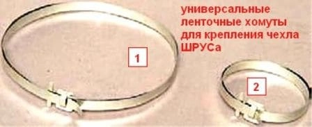
Having installed the clamp in the groove of the cover, with pliers we pull the band, compressing the clamp.
Having tightly tightened the clamp, we bend the pulled end of the band in the opposite direction.
We check the tightening of the clamp, trying to take the clamp out by its lock along the groove of the cover.
If the clamp shifts, its tightening is insufficient, and it is necessary to repeat the tightening of the clamp.
We install the rear wheel drive in the reverse order.
Removing the inner joint, replacing the cover
We remove the rear wheel drive, as described at the beginning of the article.
We lay the drive on the workbench.
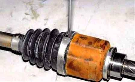
Having directed the blade of a flat screwdriver into the joint of the clamp lock, we strike with a hammer on the handle of the screwdriver.
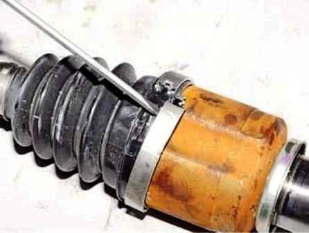
We open the lock of the large clamp.
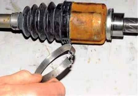
We remove the clamp.
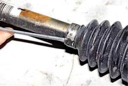
With a screwdriver we open the lock of the small clamp.
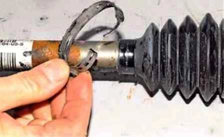
We remove the small clamp. We pull the cover off the joint body.
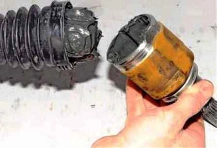
We remove the joint body.
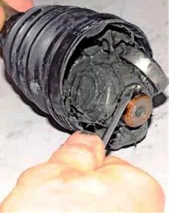
We prise up the circlip with a screwdriver.
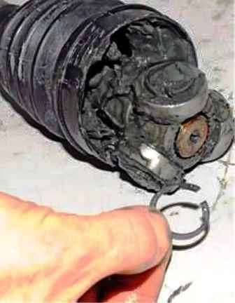
We take the retainer out of the groove on the shaft.
We remove the tripod from the shaft.
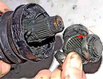
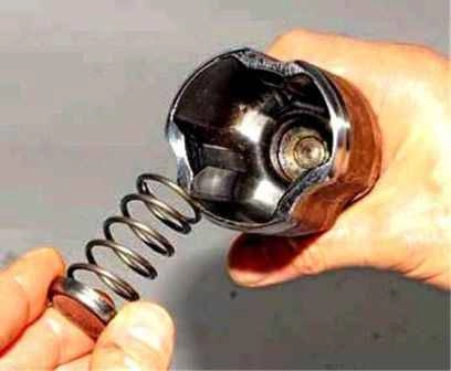
We take out the spring together with the thrust washer.
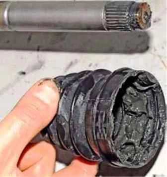
We remove the cover from the shaft.
We remove the old grease from the joint body and wash it in kerosene.
We wipe the joint with a rag and blow it with compressed air.
We inspect the rollers, the needle bearings of the tripod and the inner cavity of the joint body.
The rollers of the tripod must rotate on the needle bearings freely, without jamming.
Scores, dents, cracks, traces of corrosion on the joint elements are not allowed — we replace such a joint.
Before installing the new joint cover we apply a small amount of grease to the end face of the shaft.
Having put the cover on the shaft, we place its belt under the small clamp in the groove of the shaft.
We place half of the recommended volume of the required grease and evenly distribute it in the cavity of the joint body, and the other half — in the cavity of the cover.
We install a new circlip in the groove of the shaft.
We put the joint body on the tripod and pull the cover onto the joint body, placing the belt of the cover under the large clamp in the installation groove of the body.
We secure the joint cover with new clamps.
We install the rear wheel drive in the reverse order.


